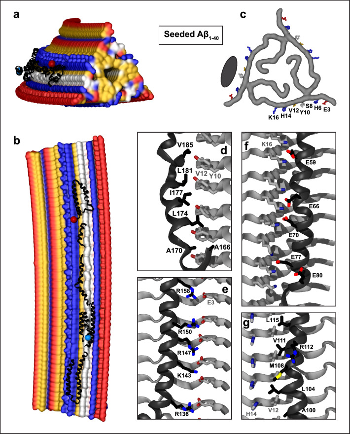
Fig. 4.
Structural model of apoE docked onto Aβ1-40 fibrils obtained by seeding using AD tissue-derived seed. The model was obtained using apoE segments shown in Supplemental Fig. 2d–h and the fibril structure (PDB ID: 2M4J). Segment positions are compatible with full-length apoE. a, b Top and side views of the docking model with apoE in black ribbon and amyloid fibril in surface representation. c Top view of one filament layer main chains. ApoE-coordinating residues E3, H6, S8, Y10, V12, H14, and K16 are indicated. Black oval indicates docked apoE. Panels d–f show apoE–amyloid contacts within ~ 5 Å in selected regions (apoE—black, Aβ—gray). d Y10, V12 ladder in Aβ1-40 interacts with the hydrophobic helical face from the apoE “lock” region. e E3 ladder in Aβ1-40 forms favorable ionic interactions including potential salt bridges with basic residues from apoE helix 4. f K16 ladder in Aβ1-40 forms favorable ionic interactions including potential salt bridges with acidic residues from apoE helix 2. g Hydrophobic residues of apoE helix 3 interact with residue ladders V12 and H14 in Aβ1-40. Side chain of 112 (R112 in apoE4) projects away from amyloid

