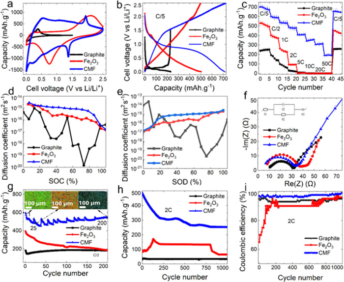
Figure 2.
(a) CV of the CMF anode compared with slurry cast control counterparts at 10 mV·s–1; (b) voltage profile of coin cells using either the CMF or slurry cast anodes at C/5; (c) rate capability test of CMFs and control electrodes; (d) Li ion diffusion coefficient of CMFs and control electrodes processed by slurry casting obtained from GITT curves for state of charge (SOC); (e) Li ion diffusion coefficient obtained from GITT for state of discharge; (f) resistivities of CMFs and the controls by means of EIS; (g) long-term cycling of CMFs and controls at C/2 rate: CMF fiber structures at three different cycles (1, 25, and 200) are shown from the X-ray microcomputed tomography (XCT) reconstructed images within the plot itself (in these images, colors represent the fiber orientations whereby green is horizontal, blue is vertical, and red is diagonal, respectively); (h) long-term cycling up to 1000 times of Li ion coin half cells at 2C using three different anodes; (i) Coulombic efficiencies for cycling Li ion coin cells up to 1000 times, showing excellent stability of CMF anodes at a high C-rate.

