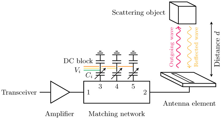
Figure 1.
Schematic representation of the system setup. The amplifier is connected to the transceiver of the communication/sensing system. The matching network is deployed between the amplifier at port 1 and an antenna at port 2. It performs tuning via three varactors at ports 3, 4, and 5. Objects near the antenna reflect parts of the outgoing waves and detune the antenna, which is then compensated by controlling the capacitance of the varactors , through voltages .

