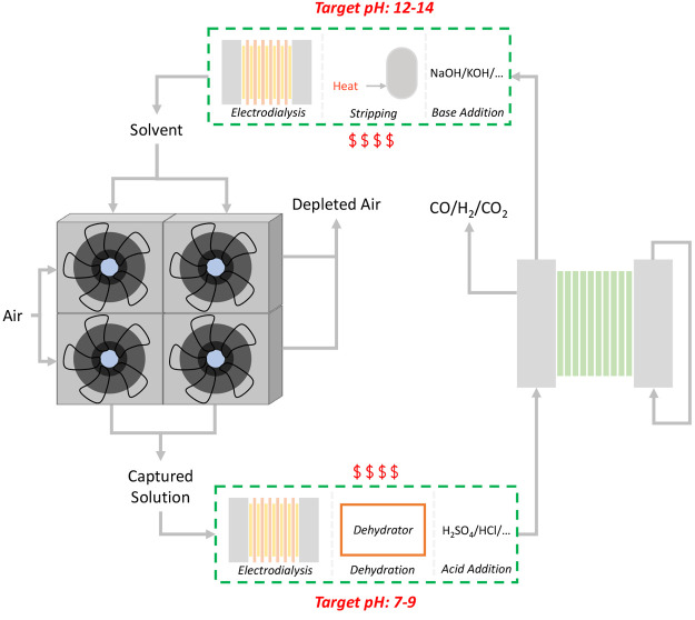
Figure 6.
Schematic of the literature-proposed integration route, with some potential solutions shown inside the green dashed boxes. On the left side, we show the air contactors and on the right side are the (bi)carbonate electrolyzer stacks. At the top and bottom, we show potential solutions that could satisfy the different pH requirements of the capture and conversion processes, which include electrodialysis, evaporator, and an acidic stream on the bottom and electrodialysis, a stripping/heating step, and a basic stream on the top.

