Figure 11.

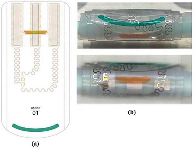
(a) Electrode drawing showing electrode contact areas above in a tripolar configuration and conductive paths to the PV die pads. Colored outer (orange) and inner (green) flaps must ease manipulation; (b) Electrode photographs.

(a) Electrode drawing showing electrode contact areas above in a tripolar configuration and conductive paths to the PV die pads. Colored outer (orange) and inner (green) flaps must ease manipulation; (b) Electrode photographs.