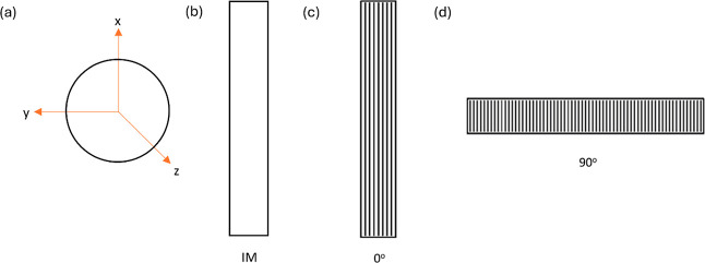
Figure 6.
Schematic illustration of orientation of x, y, and z axes in (a) pole figure, (b) IM sample, (c) 3D printed (0° printing direction) sample, and (d) 3D printed (90° printing direction) sample [please note that the directions of x, y, and z axes shown in Figure 3.3 (a) apply to the rest of Figures 3.3(b), 3.3(c), and 3.3(d) too.].

