
Extended Data Figure 2 |. PFNd and PFNv activity bumps in the bridge are phase aligned with the EPG heading signal.
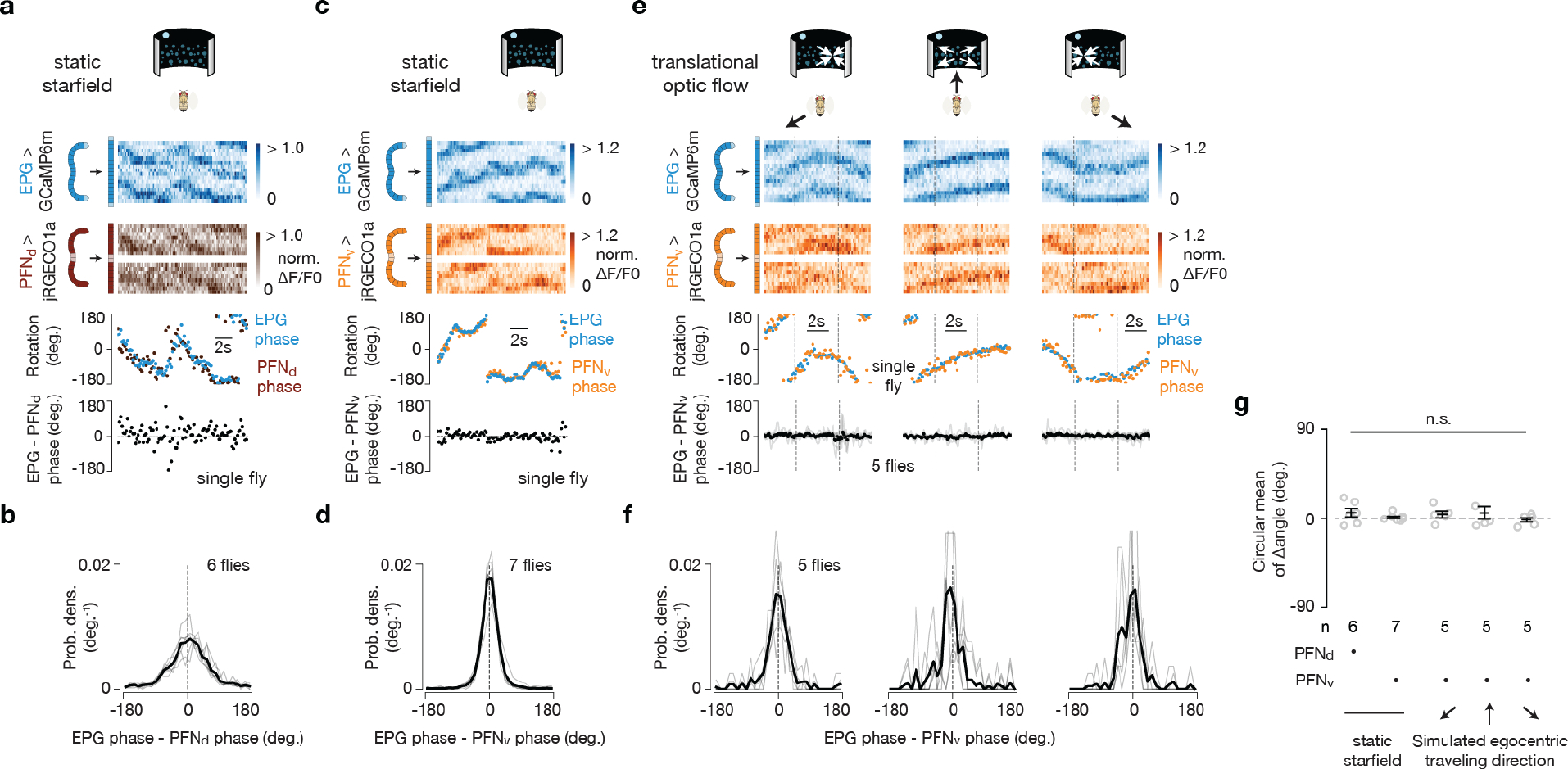
a, Sample trace, in tethered flight without optic flow, of simultaneously imaged GCaMP6m in EPGs and jRGECO1a in PFNds reveals that the activity bumps of these two cell classes are phase aligned in the bridge. b, Probability distribution of the EPG - PFNd phase in tethered flight without optic flow. In this panel and throughout, the single fly data are in light gray and the population mean is in black. c-d, Same as panel a-b, but for GCaMP6m in EPGs and jRGECO1a in PFNvs. e, Top three rows, sample trace of simultaneously imaged GCaMP6m in EPGs and jRGECO1a in PFNvs in a tethered, flying fly experiencing optic flow (in the time window bracketed by the vertical dashed lines) with foci of expansion that simulate the following directions of travel: −120°, 0° (forward), 120°. Bottom, circular-mean phase difference between EPGs and PFNvs. f, Probability distribution of the EPG - PFNvs phase under three optic flow conditions. g, Circular mean of the EPG – PFN phase ad s.e.m. under different visual stimulus conditions. Watson-Williams multi-sample tests, P>0.66 when comparing any experimental group with 0°. Note that we only collected a full EPG-PFN, dual-imaging data set with optic flow (moving dots) with PFNvs because, for reasons that are not fully clear, the jRGECO1a signal was too weak in PFNds to properly estimate the PFNd phase outside of the context of stationary dots (i.e., during optic flow). When imaging PFNds with a split-Gal4 driver and with GCaMP rather than with jRGECO1a (e.g., Fig. 3j-l), the signal is much brighter.