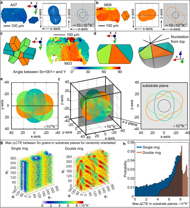
Fig. 8. Calculated connections between tin orientations and CTE mismatch.
a, b Two single-grain examples: Sn IPF orientation map, unit cell, 3D CTE ellipsoid and 2D CTE in the substrate plane. c A beachball joint coloured by angle between Sn〈001〉 and Y plus cyclic Sn unit cells, d the geometric model at different viewing angles, e corresponding 3D CTE ellipsoids in the EBSD mapping coordinates, f 3D CTE triple ellipsoids at arbitrary viewing angle and 2D CTE section in the substrate (x-z) plane. g Maximum in-plane CTE mismatch in the substrate plane between tin grains in single and double ring cyclic twins calculated from 50,000 random orientations and plotted in Euler space, h histograms of the max in-plane CTE mismatch from (g). On all in-plane 2D CTE plots (with grey background), the dashed ellipse is the in-plane CTE of the package.

