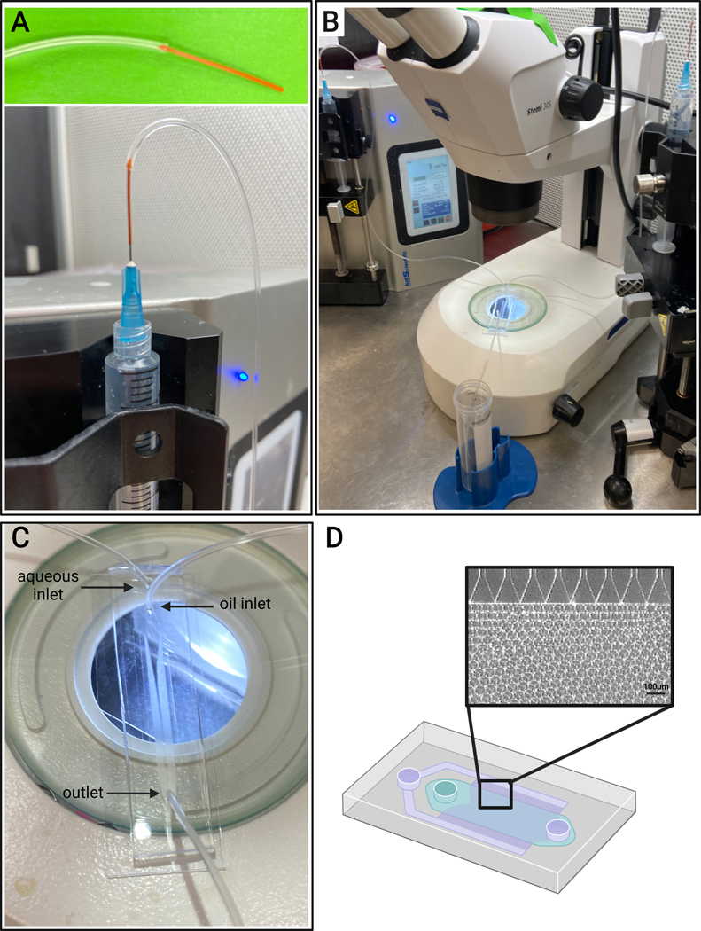
Figure 4: Microfluidic setup.

(A) Depiction of the method for connecting PEEK tubing (top) and Tygon tubing to a 25 G needle on a syringe (bottom). (B) Microfluidic setup with syringe pumps, tubing, device, and microscope. (C) Image of microfluidic device setup, with two inlets (aqueous and oil) and one outlet. (D) Schematic of the microfluidic device and representative brightfield image of expected microgel formation from the channels in a step-emulsification device.
