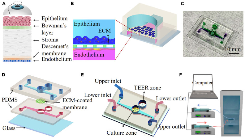
Figure 7.
Schematic showing the different layers of the human cornea and design of the cornea-on-a-chip device. (A) The anatomy of the human cornea. (B) Cross-sectional schematic diagram of the corneal chip. HCEpi and HCEnd cells are cultured on the opposite sides of a porous PC membrane coated with ECM. The membrane is sandwiched between two PDMS layers incorporated with microfluidic channels. (C) Photographs of the human cornea-chip; upper and lower microfluidic structures are indicated by using solutions with purple and green color dye. (D) Three-dimensional illustration on the device, showing the details on the structures on different layers. (E) The cornea-chip with two individual microfluidic channels and a circular hole in the middle mimics the human corneal structure. Structures for in situ TEER measurements are also fabricated on the chip. (F) Experimental setup for flow control and cell culture. The device is located in an incubator with two microchannels connected to respective syringe pumps. Creative Commons CC-BY-NC-ND license; Reprinted from Ref. [52].

