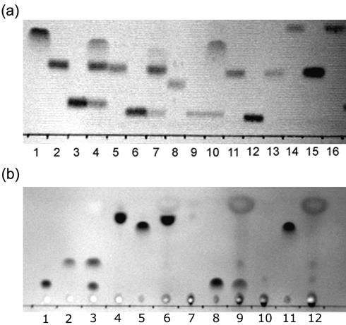
FIG. 3.
TLC plate image showing substrate specificity of YpdF. (a) The lanes are as follows (from left to right): 1, Met; 2, Met-Ala-Ser; 3, Ala-Ser; 4, Met-Ala-Ser+YpdF; 5, Met-Ser-Gly; 6, Ser-Gly; 7, Met-Ser-Gly+YpdF; 8, Met-Pro-Gly; 9, Pro-Gly; 10, Met-Pro-Gly+YpdF; 11, Met-Gly-Gly; 12, Gly-Gly; 13, Met-Gly-Gly+YpdF; 14, Met-Gly-Met; 15, Gly-Met; 16, Met-Gly-Met+YpdF. (b) The lanes are as follows (from left to right): 1, Ala-Pro-Ala; 2, Ala; 3, Ala-Pro-Ala+YpdF; 4, Tyr-Pro-Ile-Ser-Leu; 5, Tyr; 6, Tyr-Pro-Ile-Ser-Leu+YpdF; 7, Asn-Pro-Thr-Asn-Leu-His; 8, Asn; 9, Asn-Pro-Thr-Asn-Leu-His+YpdF; 10, Leu-Asp-Leu-Leu-Phe-Leu; 11, Leu; 12, Leu-Asp-Leu-Leu-Phe-Leu+YpdF.

