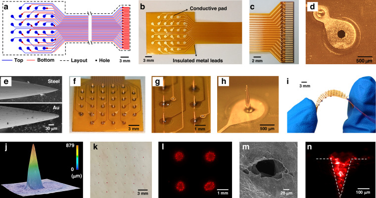
Fig. 2. Fabrication and characterization of MMA.
a The blue color indicates the top layer, the red color signifies the bottom layer, the black area indicates the drilling area, and the dotted line indicates the board frame in the flexible circuit board design layout of the MMA device. b Photograph of the flexible circuit board. c Photograph of the FPC interface. d Photograph of the exposed pads used for soldering the microneedles. e SEM images displaying the surface morphology of a microneedle before and after gold plating. f Photographs from the side of the MMA. g Enlarged photograph depicting the MMA with two microneedles spaced 3 mm apart. h Magnified optical microscope image displaying a conical microneedle tip with a height of approximately 800 μm. i Image of the MMA during bending showing that the microneedle tip remained perpendicular to the flexible substrate. j 3D reconstructed image depicting the morphology of the MMA. k Top view of porcine skin after microneedle penetration, with the indentation marked by red dye following MMA insertion. l Fluorescence images of the pig skin were captured after insertion by pressing the MMA. m SEM image of the pig skin pierced by the MMA. n Fluorescence images demonstrating the deposition of rhodamine B into the pig skin through MNE penetration

