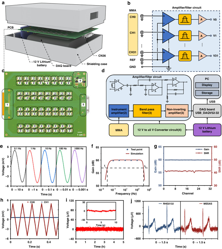
Fig. 4. Design and validation of MESAS.
a Exploded view of the MESAS, consisting of a shielding case, printed circuit board (PCB), 12 V lithium battery and DAQ board. b Wiring diagram of an amplifier/filter circuit was provided, in which thirty-two working electrodes shared a common reference electrode. c PCB layout design (top). The dashed boxes indicate the locations of the modules. d System block diagram of the MESAS. e Test signals of different frequencies were applied to one channel, and the amplified and filtered signals were detected. The gain was measured and compared with the frequency response simulation plot. f The frequency response of the amplifier/filter circuit was simulated with upper and lower frequencies set at 10 kHz and 0.01 Hz, respectively. g For the same test signal, the gain and SNR of 32 channels were measured. h A ± 5.0 mV, 100 Hz triangular wave was applied to one channel, and the signals acquired in that channel and the neighboring channels were detected. No crosstalk was observed in the neighboring channels. i Five hours of continuous basal noise detection. Inset: 10 s of basal noise. j Raw ECG data from Ag/AgCl gel electrodes were acquired using the MESAS and a commercial instrument

