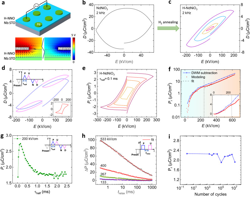
Fig. 2. Polarization measurements on H-NNO films.
a The schematic of the H-NNO device and the electric-field distribution simulated with COMSOL. The arrow size denotes the norm of the electric field and the color denotes the potential. b, c The electric displacement vs. applied electric field measured at 2 kHz for pristine NNO and H-NNO films. d The PUND measurement for the H-NNO film. The period of the half wave is 0.1 ms. Inset is the extracted PUND loop as a function of the electric field from the measurement. e PUND loops with different maximum electric fields and the same period of half wave of 0.1 ms. f Remanent polarizaton vs. electric field. Pr in blue dots is obtained from PUND loops and Pr in red dots is from modeling as described in Supplementary Note 1. Inset is an enlarged plot of Pr vs the electrield field ranging from 0 to 350 kV/cm. g Remanent polarization as a function of period of half wave with the same maximum electric field of 200 kV/cm. h as a function of trelax. is the difference of the polarization by the pulses P and U. trelax is the time interval between two pulses as shown in the inset. i Pr measured by PUND loops versus the number of switching cycles.

