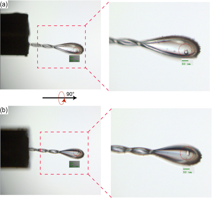
Figure 3.
Sample alignment images from the BL19U1 experimental station. (a) A sample centred in the initial position. The image shows a crystal mounted on the goniometer pin, perfectly aligned within the red circle which indicates the focus area of the beam, as shown by the green scale bar indicating 50 µm. (b) The same sample after a 90° rotation. The crystal remains precisely centred, maintaining its position within the focus area, demonstrating the accuracy of the goniometer’s rotation and the stability of the sample mounting.

