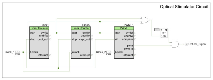
Figure A8.
Laser stimulator signal logic schematic. Digital PSoC™ Creator embedded components shown above. The two timers modulate the pulse train. The fast timer modulates the pulse duration of each train and the slow timer modulates how much time passes between each pulse train. This is permitted by the overflow of each timer. The PWM defines the laser pulsing within each pulse of the pulse train. The additional logic and the flip-flop combined modulate the signal as desired.

