Figure 3.
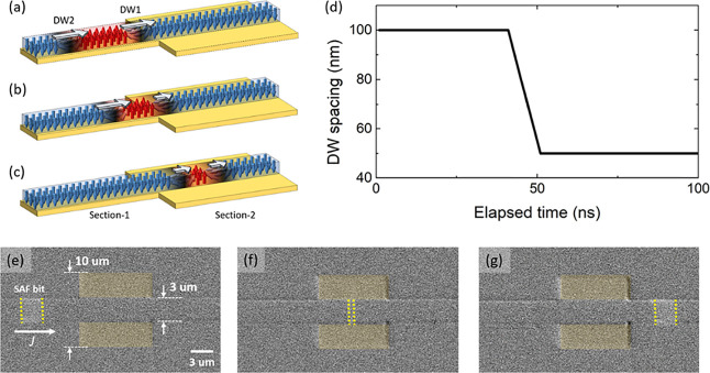
(a–c) Model for a passive DW spacing controller. The illustrations depict the shrinking of the DW spacing as it is moved from a narrow section 1 to a wider section 2 of the racetrack. As DW1 enters section 2, where the current density is lower, vDW1 (speed of DW1 at given current pulse) slows down, while DW2 keeps its original speed. The length of the white arrows in the illustrations represents the speed. As a consequence, the DW spacing shrinks. (d) Numerically simulated result for the case when a 100 nm wide bit enters a region with half the current density, i.e., half vCIDWM. (e–g) Demonstration of DW spacing control in a decompression–compression–decompression type device. The Pt width is enlarged in the middle of the structure (racetrack width of 3 μm; Pt width of 10 μm).

