Figure 4.
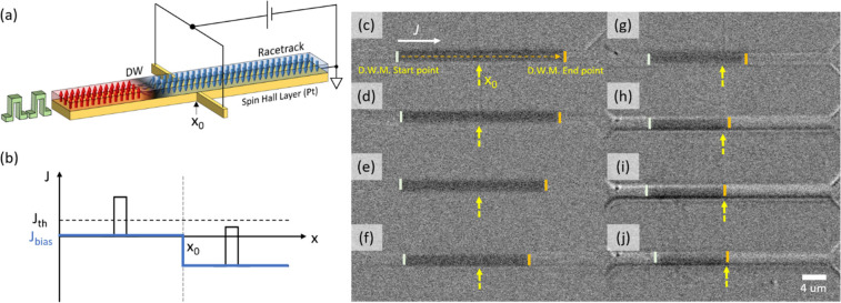
(a) Schematic illustration of active DW spacing control device. The bar across the racetrack is used for the bias point. This, in principle, can be placed under or over the racetrack. (b) Electrical potential along the racetrack upon application of Vbias. x0 indicates the bias point. Upon reverse bias, the applied pulse amplitude (forward motion) is lower than the threshold level. This stops the motion of the DW into the bias region. (c) DWM with 8 V; 5 ns; 100 pulses at zero bias. White and orange bars indicate the starting and end points of the DW motion. After placing the DW to the original position, the same pulses were injected upon application of bias (d) −1, (e) −2, (f) −3, (g) −4, (h) −5, and (i) −6 V. At zero bias, the DW was shifted 29 μm upon 100 injected pulses, so that vCIDWM = 58 m s–1. As the reverse bias is increased, the vCIDWM in the biased region was found to be 58 m s–1, 50 m s–1, 42 m s–1, 10 m s–1, and 0 m s–1 with Vbias = −1, −2, −3, −4, −5, and −6 V, respectively. (j) Note that even after injecting 1000 pulses, the DW stays at the bias point. This confirms that the DW does not propagate into the bias region at Vbias = −6 V.

