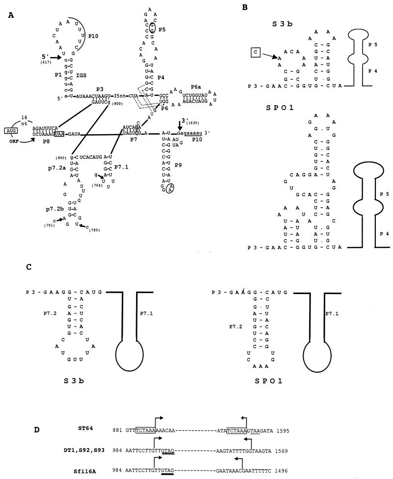
FIG. 3.
(A) Secondary structure prediction for the S3b intron represented according to the structural convention of Burke et al. (8). Large arrows indicate the 5′ and 3′ splice sites. The exon and intron sequences are denoted by lower- and uppercase letters, respectively. Underlined sequences denoted with P10 indicate the regions which can anneal to form P10. Predicted tertiary interactions are indicated by dotted lines (P4/J6-7 and J3-4/P6) and by circled nucleotides (P5/P9). The shaded nucleotides in P7 represent the putative guanosine binding site. The start and stop codons of orf 253 are boxed. Sequence differences within the structural regions of phage Sfi16A (nucleotide [nt] positions 764 and 789), S92 (nt positions 764 and 791), ST64 (nt positions 764 and 789), and DT1 (nt position 791) introns are indicated by small arrows. The two possible locations for the G residue (nt position 800) are indicated. Nucleotide positions are numbered according to the S3b sequence (accession no. AF148561). The numbering begins with the start codon of orf 207. (B) Folding of the joining region between P3 and P4 (J3-4) of the S3b intron and the intron of B. subtilis phage SPO1. The sequence difference between both the phage ST64 and Sfi16A introns and the S3b intron is boxed. A belongs to phage S3b. (C) Alternative folding of a P7.2 stem for the phage S3b intron in comparison with the P7.2 stem for the phage SPO1 intron. (D) Comparison of the deletion points of the variant introns of phages ST64, DT1, S92, S93, and Sfi16A. The sequence given is that of S3b. Bent arrows indicate the region which is deleted in the respective phages. The 6-bp direct repeat flanking the deletion in the phage ST64 intron is boxed, and the stop codon of orf 253 is underlined. The GTAG sequence matching the intron insertion site (see Fig. 6) is doubly underlined in variant introns of phages DT1 and Sfi16A.

