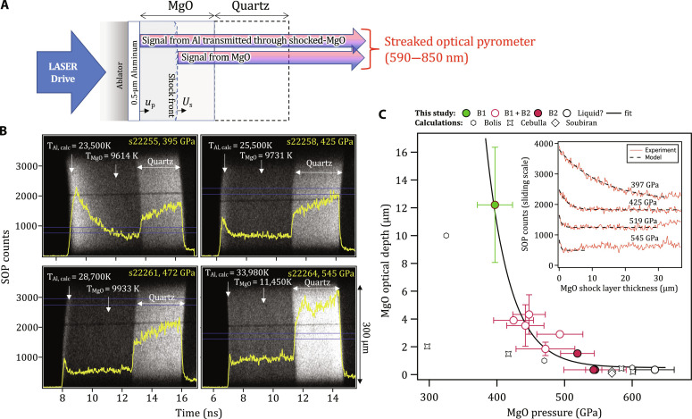
Fig. 4. Measurement of optical depth in shocked MgO as a function of pressure.
(A) The target design consists of a polyimide ablator, a 0.5-μm Al layer directly coated on to an 80-μm-thick MgO [100] single crystal and a 60-μm-thick quartz layer. As the shock propagates through the target assembly, thermal emission from the hot, compressed Al layer, ∼constant over the lifetime of the experiment, is transmitted and attenuated through the shocked-MgO crystal and recorded by the SOP diagnostic. The raw data from the SOP for four different pressures are shown in (B) with intensity lineouts, taken from the region defined by two horizontal blue lines, shown as the bold yellow curves. In each case, the calculated Al shock temperature is shown (79) as well as the measured MgO shock temperature. (C) (Inset) The optical depth is determined by considering the time taken for Al thermal emission to drop from a peak level to 37% of the peak, while the associated MgO shock-thickness is calculated from US and uP estimates. (Main plot) Estimated values of optical depth are plotted along with calculations based on theory (15, 19, 72) (see Materials and Methods).

