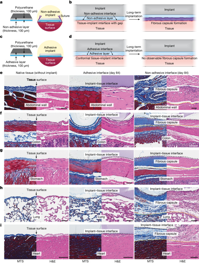
Fig. 1. Adhesive anti-fibrotic interfaces.
a,b, Schematic illustrations of a non-adhesive implant consisting of a mock device (polyurethane) and a non-adhesive layer (a) and long-term in vivo implantation with fibrous capsule formation at the implant–tissue interface (b). c,d, Schematic illustrations of an adhesive implant consisting of the mock device (polyurethane) and an adhesive layer (c) and long-term in vivo implantation without observable fibrous capsule formation at the implant–tissue interface (d). e–i, Representative histology images stained with Masson’s trichrome (MTS) and haematoxylin and eosin (H&E) for native tissue (left), the adhesive implant (middle) and the non-adhesive implant (right) collected on day 84 post-implantation on the abdominal wall (e), colon (f), stomach (g), lung (h) and heart (i). Black and yellow dashed lines in the images indicate the implant–tissue interface and the fibrous capsule–tissue interface, respectively. The experiment in e–i was repeated independently (n = 4 per group) with similar results. Scale bars, 50 μm (e–g, left and middle; h), 100 μm (e, right; i), 200 μm (f, right), 150 μm (g, right).

