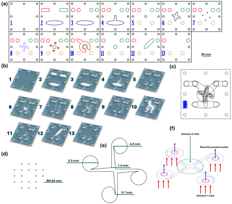
Figure 1.
(a) Proportional 2D schematic representation of the microfluidic platform individual layers; Scale bar: 20 mm; (b) Schematic 3D representation of the microfluidic platform individual layers; (c) Schematic 2D overlayed view; (d) Reactant inlets dimensions (layer 9). (e) Vortex mixing chamber dimensions (layer 8); (f) Overlayed reaction area; red—channels for reagent solution 1 (layer 9); green—channel for reagent solution 2 (layer 9); purple—vortex mixing chamber (layer 8); violet—collecting channels (layer 7). Colors: red—inlet channels for solution 1 (iron precursors path), green—inlet channels for solution 2 (alkaline medium path), purple—vortex mixing chamber, violet—product collecting channels and chamber, orange—outlet channels.

