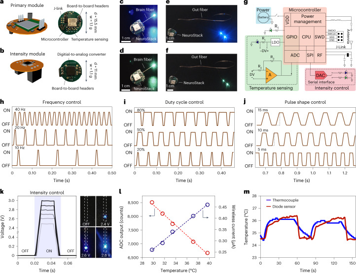
Fig. 4. NeuroStack, a custom designed modular wireless circuit for microelectronic fibers, allows programmable light delivery and physiological recording.
a,b, Schematic illustration (left) and digital images (right) highlighting important circuit components of a primary module (a) and intensity module (b). c–f, Images showing independent wireless control of blue (c) and green (d) µLEDs within a brain fiber and blue (e) and green (f) µLEDs in the gut fiber. g, Circuit layout of NeuroStack highlighting the power management block, temperature sensing block and intensity control block. h, Real-time control of optical stimulation frequency between 10 and 40 Hz. i, Real-time control of optical stimulation duty cycle between 20% and 80%. j, Optical pulse shaping through control of pulse rise and fall times between 5 and 15 ms. k, Intensity module permits real-time control of µLED brightness with corresponding photographs at 2.4-, 2.6- and 2.8-V bias. l, Calibration of the fiber thermal sensor using NeuroStack under steady-state conditions of 29–40 °C. m, Wireless recording of temperature transients with the thermal sensor in the microelectronic fiber and its comparison with a commercial thermocouple in wired mode. d, diameter; w, weight; CPU, central processing unit; DAC, digital-to-analog converter; GND, ground; GPIO, general-purpose input/output; LDO, low-dropout regulator; RF, radio frequency; SPI, serial peripheral interface; SWCLK, serial wire clock; SWD, serial-wire debug; SWDIO, serial-wire debug data input/output ; VDD, voltage drain-to-drain; ADC, analog-to-digital converter.

