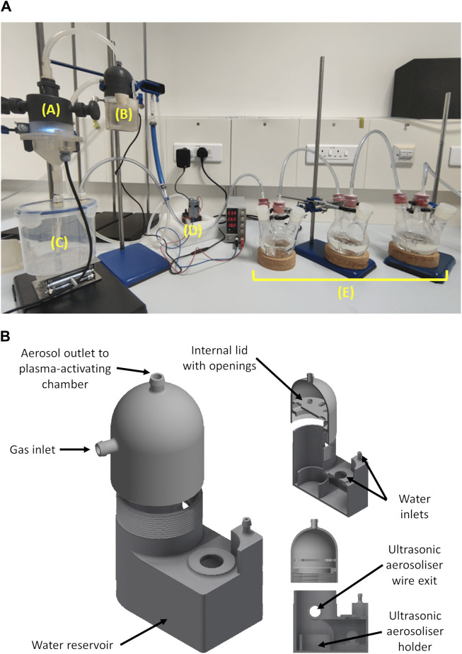
FIGURE 1.
A photo (A) of the developed plasma-activated aerosol setup in operation showing the plasma-activating chamber (A), aerosol generating chamber (B), aerosolizing chamber (C), air pump (D) and bubbling flasks (E). The schematic diagram (B) shows the aerosol generating chamber with cross sections showing the internal compartments.

