Abstract
Objective
AO/OTA 31‐A3.3 intertrochanteric fracture is the most unstable type of intertrochanteric fracture, with a high rate of postoperative complications and implant failure. We have designed a new intramedullary fixation, proximal femoral totally bionic nail (PFTBN), for the treatment of A3.3 intertrochanteric fracture. To test its biomechanical performance, we adopted the method of finite element analysis and compared PFTBN with proximal femoral nail antirotation (PFNA) and proximal femoral bionic nail (PFBN, another internal fixation we previously designed for stable intertrochanteric fractures).
Methods
Mimics, 3‐matic, ANSYS, and other software were used to construct a highly precise and realistic 3D digital model of the human femur. An AO/OTA 31‐A3.3 intertrochanteric fracture of the femur was constructed according to the 2018 classification of AO/OTA, and then assembled with PFNA, PFBN and PFTBN models, respectively. The stress distribution and displacement distribution of the three groups of constructs were tested under three times the body weight load and one‐foot standing configuration.
Results
In terms of maximum stress and maximum displacement, the PFTBN group outperforms the PFBN group, and the PFBN group, in turn, surpasses the PFNA group. The maximum stress of PFTBN group was 408.5 Mpa, that of PFBN group was 525.4 MPa, and that of PFNA group was 764.3 Mpa. Comparatively, the maximum stress in the PFTBN group was reduced by 46.6% when contrasted with the PFNA group. Moreover, the stress dispersion within the PFTBN group was more evenly distributed than PFNA group. Regarding maximum displacement, the PFTBN group displayed the least displacement at 5.15 mm, followed by the PFBN group at 7.32 mm, and the PFNA group at 7.73 mm. Notably, the maximum displacement of the PFTBN group was 33.4% less than that observed in the PFNA group. Additionally, the relative displacement between the fragment and implant at the tip of pressure screw or helical blade was 0.22 mm in the PFTBN group, 0.34 mm in the PFBN group, and substantially higher 0.51 mm in the PFNA group.
Conclusion
The “lever‐reconstruction‐balance” theory provides a new perspective for us to understand the mechanical conduction of the proximal femur. Compared with PFNA, in treating A3.3 intertrochanteric fractures PFTBN can better reconstruct the function of lateral wall, restore physiological mechanical conduction, increase postoperative stability, and finally reduce the risk of postoperative cut‐out and implant failure. It might be a better alternative for the treatment of A3.3 intertrochanteric fracture.
Keywords: Finite element analysis, Internal fixation, Intertrochanteric fracture, Lateral wall, Proximal femoral totally bionic nail
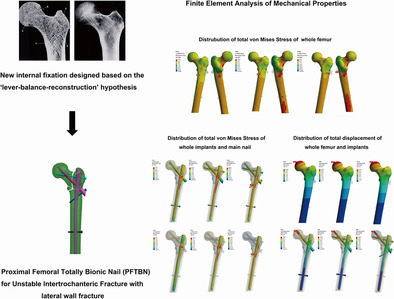
Guided by “lever‐reconstruction‐balance” hypothesis, we have engineered proximal femoral totally bionic screw (PFTBN) aimed at reconstructing the mechanical role and functionality of the lateral wall. Using the finite element analysis method, PFTBN outperforms proximal femoral nail antirotation (PFNA) and proximal femoral bionic nail (PFBN) concerning mechanical properties and stability when utilized in the treatment of 31A3.3 intertrochanteric fractures.
Introduction
Hip fracture causes huge social burden, and the number of hip fractures may increase significantly for a long time into the future. 1 , 2 , 3 Intertrochanteric fractures account for about 50% of hip fractures 4 , 5 , 6 with a higher average age 7 , 8 and higher mortality rate 9 , 10 compared with that of patients with femoral neck fractures, thus causing greater impact on life expectancy and living quality of patients. Unstable intertrochanteric fracture currently accounts for the highest proportion of intertrochanteric fracture, and has a rising trend year by year, 11 among which AO/OTA 31‐A3.3 is the most unstable type with medial wedge fragment and lateral wall fracture. Because of the complex fracture shape, poor arrangement of fragments and poor postoperative stability, there are many difficulties in the treatment of A3.3 intertrochanteric fractures. At present, there is no consensus on the best choice for its treatment. The current treatment methods mainly include intramedullary fixation like PFNA, InterTan, Gamma nail, and extramedullary fixation like dynamic hip screw (DHS), sliding hip screw (SHS), dynamic condylar screw (DCS), dynamic hip locking plate (DHLP), and so on. 12 Extramedullary fixation such as SHS, DHS, and DHLP was once the preferred option, but the incidence of postoperative adverse outcomes such as cut‐out, coxa vara, 12 secondary operation, 13 and fracture nonunion 14 was high. With the emergence and development of intramedullary fixation, intramedullary fixation has become the norm. A large number of systematic reviews and meta‐analysis show that intramedullary fixation is more effective in the treatment of unstable intertrochanteric fractures, with lower postoperative complications and secondary operation rates, 14 , 15 , 16 , 17 but there are also reports showing that the postoperative complications rate of A3 type of intertrochanteric fractures treated with traditional intramedullary fixation can still reach 20%. 18 Some researchers still believe that compared with PFNA, Gamma nail and so on, extramedullary percutaneous compression plate (PCCP) is the best choice for the treatment. 19 Therefore, it is meaningful to explore a more effective treatment.
The lateral wall is key to the postoperative stability of unstable intertrochanteric fracture. In 2004, Gotfried first emphasized the important role of the lateral wall in the postoperative stability of unstable intertrochanteric fracture. 20 After that, more researchers confirmed that patients with incomplete or ruptured lateral walls will present a significant increase in the incidence of postoperative implant failure, 13 reoperation 21 and secondary fracture. 22 The implant failure includes cut‐out, nail withdrawal, loosening, and proximal femur collapse. 14 , 20 , 23 Even if the lateral wall is intact, if the thickness is not enough (< 20.5 mm), secondary fractures of the lateral wall, 22 and greater trochanter iatrogenic fractures 24 are more likely to occur after operation. Therefore, when exploring more effective methods for the treatment of A3.3 intertrochanteric fractures, strengthening fixation and repair of the lateral wall is a crucial direction. Strategies like combining intramedullary fixation with cerclage wire for lateral wall reinforcement, 25 and integrating intramedullary fixation with lateral wall plates for enhanced fixation 26 , 27 , 28 have been tried, but there may be disadvantages such as the operation being too complicated and the operation taking a long time, which may cause greater trauma.
To solve the above problems, our research team proposed the theory of “lever‐reconstruction‐balance” to redescribe the mechanical conduction relationship of the proximal femur, 29 and developed a new intramedullary fixation for the treatment of A3.3 intertrochanteric fractures, namely, proximal femoral totally bionic nail (PFTBN). The key innovation of this new intramedullary fixation is that the redesigned neck screw structure simulates the crossed trabecular structure of the proximal femur, and the lateral wall screw is used to reconstruct the mechanical conduction of the lateral wall. This design has been patented in China (ZL202211568121.7).
To compare biomechanical performance of PFNA, PFBN, and PFTBN for treating A3.3 intertrochanteric fractures, the study employed the finite element analysis. Our hypothesis was that the PFTBN can improve the postoperative stability of A3.3 intertrochanteric fracture and reduce the risk of postoperative implant failure.
Method
“Lever‐reconstruction‐balance” Theory
Previous studies have shown that trabeculae in cancellous bone also play a considerable role in the strength and load‐bearing of the femur. 30 , 31 , 32 In the proximal femur, there are five groups of trabeculae that play an important role, which are primary pressure trabeculae, primary tension trabeculae, secondary pressure trabeculae, secondary tension trabeculae, and greater trochanter trabeculae 33 , 34 (Figure 1, upper left). According to Wolff's law, trabeculae are driven by external loads, and their spatial distribution, thickness and strength change correspondingly with the direction and strength of principal stress in the proximal femur to form a special three‐dimensional structure. 35 This view has also been confirmed by other researchers. 36 Therefore, the location and direction of the five groups of trabeculae reflect the concentrated location and direction of internal stress in the proximal femur. Cancellous bone and cortical bone jointly realize the physiological function of stress conduction of proximal femur. Wolff also mentioned that the trabecular structure at the proximal femur is shaped like a pillar and supporting rod for fixing a gas lamp (Figure 1, upper right), and tensile and compressive stresses are conducted through the trabecular path. 35 , 37 We believe that within a certain range, as the support point of the pillar is closer to the position under pressure (Figure 1, lower left, point A), its load‐bearing capacity becomes stronger, similar to a special lever. The closer the fulcrum (Figure 1, lower left, point A/B/C) is to the place where the force is applied, the shorter the arm that can produce moment would be. The distal end of the fulcrum forms the resistance arm (Figure 1, lower left, triangle area). So, we proposed the “lever‐reconstruction‐balance” theory. We believe that there is a special lever in proximal femur, and the fulcrum is located in the femoral head at the junction of the primary tension trabeculae and the primary pressure trabeculae. When gravity acts on the femoral head, the gravity is close to the fulcrum, and the moment arm is short, forming a laborious lever. As a result, the internal stress on the resistance arm is small, which also explains the strong load‐bearing capacity of the hip joint which can bear a load of more than four times of body weight during walking. 38 When the intertrochanteric fracture occurs, the lever conduction structure inside the proximal femur is destroyed and cannot be effectively reconstructed with a traditional intramedullary nail, and the junction of the neck screw and the intertrochanteric fracture line becomes a new fulcrum. At this time, gravity is far away from the fulcrum, forming a labor‐saving lever, resulting in the increase of stress at the distal end of the fulcrum. When the stress cannot be balanced, the internal fixation system faces the risk of failure. We preliminarily verified our theory through the mechanical analysis of different coronal posture of femur and the finite element analysis of proximal femoral bionic nail (PFBN) which simulates the structure of tension and pressure trabeculae of the femur. 39 , 40 Lateral wall fracture destroys the stable mechanical conduction system of the lateral femoral cortex (Figure 1, lower right) and also loses the support of the secondary trabeculae, so we designed the PFTBN which can reconstruct the mechanical conduction of the lateral wall. On the basis of the traditional PFNA design, there are five components of PFTBN: the pressure screw simulating primary pressure trabeculae replaced the helical blade (purple neck screw), the tension screw (light blue neck screw) simulating primary tension trabeculae which is perpendicular to the main nail and is placed from the lateral side of the greater trochanter, the lateral wall screw (blue oblique screw) simulating lateral wall added from the tail of the pressure screw perpendicularly passing through the lateral cortex and anchored to the medial cortex and distal locking screw (Figure 2).
FIGURE 1.
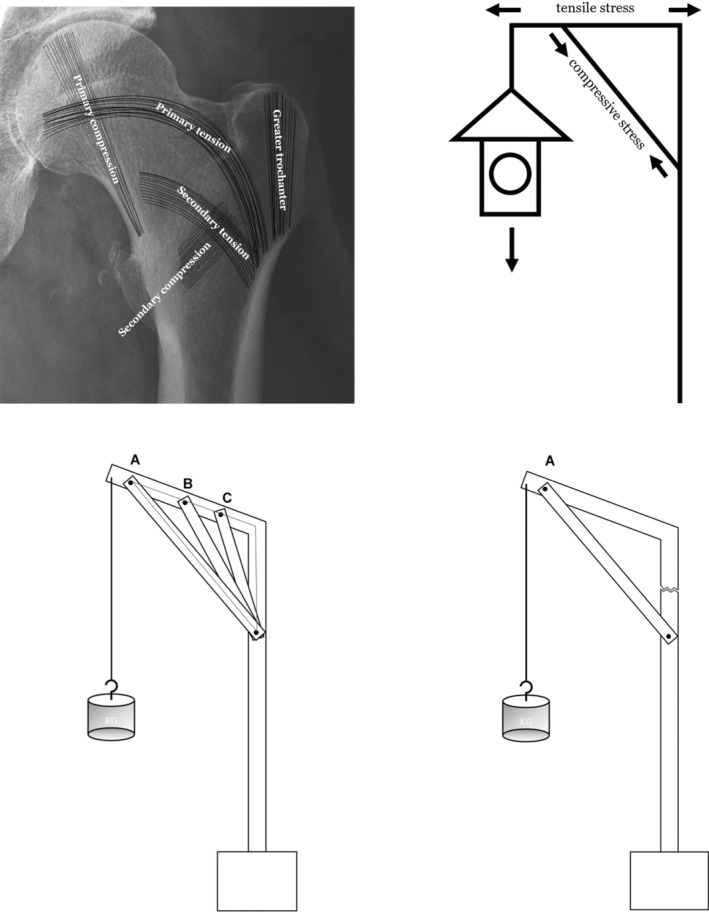
Schematic diagram of proximal femoral trabecular structure, conduction of internal stress, and structure of special lever within proximal femur.
FIGURE 2.
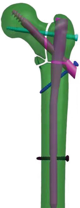
Designed configuration of PFTBN. There are five components, main nail, pressure screw, tension screw, lateral wall screw and distal locking screw.
Establishment of a High‐precision, High‐fidelity 3D Digital Model of the Human Femur
An adult male femur (43 years, left side, without the history of fracture, osteopathy, tumor, bone defect, and surgery in the femur) was selected as the study object. High‐resolution CT was employed to perform thin‐layer scanning of the complete femur, and digital imaging and communications in medicine (DICOM) format data were obtained.
The DICOM data were imported into Mimics 21.0 software (Materialise, Leuven, Belgium), and the CT Bone Segmentation algorithm in the Advanced Segmentation tool was applied to extract the femur mask. Edit Mask tool is used to fill holes or remove superfluous parts in the corresponding positions of DICOM images in each layer, and the filled mask is materialized by Calculate Part to generate femur entity and export the model as STL file.
The model was imported into 3‐MATIC 13.0 software (Materialise, Leuven, Belgium) for further repair: Laplacian smoothing method was used for 10 iterations to smooth the surface; The Remove Spikes tool was used to remove burrs. The 3D model of the repaired femur is finally obtained. The preliminary 3D mesh model is composed of triangular surfaces. If triangular surfaces have problems such as different shapes and sizes, cross and overlap, a series of methods such as Smooth, Reduce, and AutoRemsh can be used to optimize the mesh. After the processing is completed, export the STL file to Geomagic Studio 13.0, and use the precise surface command to generate the solid file as STP format.
Digital Construction of Three Kinds of Intramedullary Fixation Systems
Laser scanning was used to measure the length, diameter, angle, and various other parameters of the standard PFNA. Subsequently, the initial design parameters of both PFBN and PFTBN were directly imported into UG 10.0 software to create three distinct configurations for the intramedullary nails.
Construction of Fracture Model and Assembly of Internal Fixation
Import the STP format femur file created above into the UG10.0 software, segment the proximal femur domain according to the 2018 version the AO classification, establish an AO/OTA 31‐A3.3 intertrochanteric fracture digital model, and assemble it with the PFNA, PFBN, and PFTBN models, respectively. Use the rotation and translation function in the software to adjust the position of the internal fixation according to the operating instructions of the implant so that it is consistent with the surgical fixation position. The fracture model and the implant model are assembled through Boolean operations so that the outer surface of the implant model is in surface contact with the fracture model.
Material Assignment and Model Meshing
Import the above files into the static structure module of ANSYS Workbench 2023R1 software (ANSYS, Cannonsburg, PA, USA) to assign materials. The elastic modulus of the cortical bone of the femur is set to 17,000 Mpa, the elastic modulus of the cancellous bone is 445 Mpa, and the Poisson's ratio is 0.3 and 0.2, respectively. Set the elastic modulus of internal fixation titanium alloy to 113,800 Mpa and Poisson's ratio to 0.342. 41 The body mesh of femur model and internal fixation was divided into a Tet10 mesh with a mesh size of 2 mm.
Boundary Condition Setting
Set the contact conditions (friction contact: The coefficient of friction between bone and bone was 0.46, the coefficient of friction between bone and implants was 0.3, and the coefficient of friction between implants was 0.2 41 ). The load was set at 3 times body weight (3BW, 2100 N). The inclining angles of the coronal and sagittal planes was set at the adduction angle α (10° ± 1°) and the forward flexion angle β (9° ± 1°) to simulate the posture of standing on one foot. The direction of load is straight down. The top surface of the femoral head, spanning a diameter of 30 mm, serves as the load‐bearing surface, while the area extending 10 cm in height at the bottom of the femoral condyle is designated as the fixation surface.
Observation Index
First, the von Mises stress distribution, peak value and its position of the implants and femurs were obtained to analyze the risk of implant failure. Second, the displacement distribution, peak value and its position of femurs and implants were measured to evaluate the postoperative stability. On this basis, the effect of stress dispersion and the relative displacement between femur and implant at the tip of helical blade or pressure screw were analyzed.
Result
Stress Analysis
Total von Mises Stress Analysis of Implants
The results (Figure 3) showed that the highest von Mises stress values within all three groups of constructs are observed at the main nail. Specifically, for PFNA and PFBN, the peak stress occurs at the junction of the main nail with either the helical blade or the pressure screw, registering a maximum stress of 764.3 MPa for PFNA and a maximum total stress of 525.4 MPa for PFBN. In contrast, PFTBN exhibits its maximum stress at the juncture of the lateral wall screw and the inner aspect of the main nail, with a significantly reduced maximum stress of only 408.5 MPa. This represents a 46.6% reduction when compared with PFNA. Regarding the distribution of von Mises Stress throughout the model, PFNA exhibits the most concentrated areas of high‐level stress (indicated by red and orange stress regions) with a relatively smaller dispersion area. In contrast, both PFBN and PFTBN show larger areas of high‐level stress dispersion, effectively distributing stress not only to the main nail but also to the newly designed nails (tension screws, pressure screws, and lateral wall screws).
FIGURE 3.
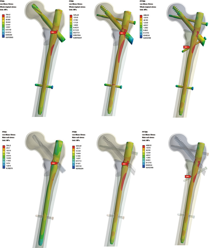
Total von Mises Stress distribution nephogram of whole implants and main nail in PFNA group, PFBN group, and PFTBN group under three times body weight load.
The sectional stress distribution of the three models showed that the high stress of main nail is mainly concentrated on the medial side slightly below the medial wedge fragment (Figure 4). It is confirmed that the existence of medial wedge fragment makes the medial support disappear, thus forming a strong varus tendency during the one‐foot stance simulation.
FIGURE 4.
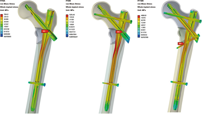
Profile map of total von Mises Stress distribution of whole implants in PFNA group, PFBN group, and PFTBN group under three times body weight load.
Neck Screw Stress Analysis
We extracted the stress distribution cloud map for the neck screw (Figure 5). Among the three groups, it is evident that the PFBN group exhibits the lowest maximum stress for the neck screw, measuring 126.4 MPa. This stress is localized at the junction where the pressure screw and tension screw intersect. In contrast, the PFNA group displays a medium level of stress, with the maximum stress for the helical blade reaching 146.1 MPa, concentrated at the junction between the helical blade and main nail. Meanwhile, the PFTBN group records the highest maximum stress for the neck screw, registering at 171.23 MPa, and also localized at the junction of the pressure screw and the main nail. Considering the fact that the maximum stress observed in the whole implant of the PFTBN group is significantly lower than that of the other two groups, it is indicative of the superior mechanical properties exhibited by PFTBN enabling the effective dispersion of stress to other structural components beyond the main nail.
FIGURE 5.
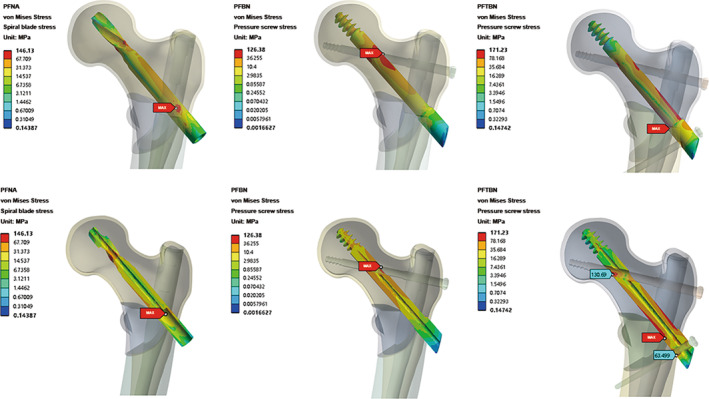
Nephogram and profile map of total von Mises Stress distribution of neck screw in PFNA group, PFBN group, and PFTBN group under three times body weight load, the bottom is profile map.
Total von Mises Stress Analysis of Femur
The result of von Mises stress cloud map analysis of the femur is close to that of implant (Figure 6). In the PFNA group, the maximum femoral stress reaches 164.9 MPa, localized beneath the lesser trochanter on the posterior side of the femur. Comparatively, in the PFBN treatment group, the maximum femoral stress registers at 125.4 MPa, situated in a similar location to that observed in the PFNA group. In the case of the PFTBN group, the maximum femoral stress is notably reduced, measuring 103.7 MPa, and is located near the lateral wall adjacent to the tail of the pressure screw. Significantly, the maximum femoral stress observed in the PFTBN group demonstrates a substantial reduction of 37.1% when compared with that in the PFNA group. Furthermore, with regard to stress distribution, the PFTBN group exhibits a more even dispersion of stress throughout the femoral head, femoral neck, femoral shaft, and calcar compared to the PFNA group.
FIGURE 6.
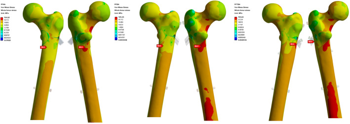
Nephogram of total von Mises Stress distribution of whole femur in PFNA group, PFBN group, and PFTBN group under three times body weight load.
Displacement Analysis
Total Displacement Distribution of Femur
The maximum displacement of the three groups occurred in the position of the femoral head subjected to the aforementioned loading conditions (Figure 7). Under identical loading conditions, the PFNA group exhibits the largest maximum displacement, measuring 7.73 mm, the PFBN group reaches 7.32 mm, while the PFTBN group demonstrates the highest resistance to deformation, recording a displacement of only 5.15 mm. This marks a significant reduction of 33.4% when compared with the PFNA group's displacement.
FIGURE 7.
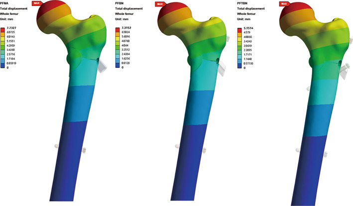
Nephogram of total displacement distribution of whole femur in PFNA group, PFBN group, and PFTBN group under three times body weight load.
Total Displacement of Implants
The visual representation of the displacement distribution of three groups is similar to that of the femur (Figure 8). Specifically, the PFNA group records the highest displacement, measuring 7.22 mm, and the PFBN group reaches 6.97 mm and in contrast, the displacement of the PFTBN group remains the lowest at 4.93 mm. Remarkably, this translates to a substantial 31.7% reduction in displacement compared to the PFNA group.
FIGURE 8.
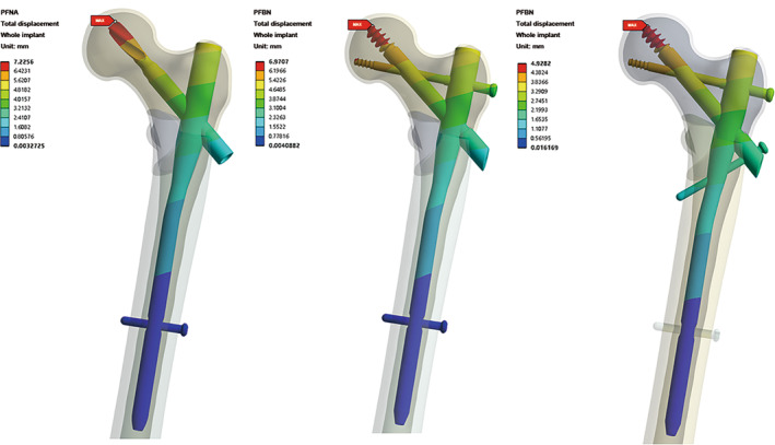
Nephogram of total displacement distribution of whole implants in PFNA group, PFBN group, and PFTBN group under three times body weight load.
Relative Displacement between Fragment and Implant
Consideration was given to the relative displacement between the tip of the helical blade or the pressure screw and the corresponding fragment. In the PFNA group, the relative displacement measured 0.51 mm. For the PFBN group, the relative displacement was slightly reduced, measuring 0.34 mm. Finally, the PFTBN group demonstrated the lowest relative displacement, recording 0.22 mm. This represents a notable reduction of 56.9% when compared with the relative displacement observed in the PFNA group.
Discussion
In this study, we constructed a finite element model of an AO/OTA 31‐A3.3 type intertrochanteric fracture, and compared the biomechanical properties of PFTBN, PFBN, and PFNA in the treatment of 31A3.3 intertrochanteric fractures. From the results, PFTBN presented better performance in terms of the peak stress, the maximum displacement and the relative displacement between fragment and implant, which suggests that PFTBN may be more suitable for the treatment of A3.3 type intertrochanteric fractures.
Risk of Postoperative Implant Failure
A3.3 intertrochanteric fracture is the most unstable type with a high risk of postoperative implant failure and secondary operation. 13 Park et al. have reported that the postoperative implant failure rate of A3.3 intertrochanteric fracture is 18%. 42 In finite element analysis, peak stress is a good index for predicting the risk of implant failure. 43 In our study, the peak stress of implant in PFTBN group is only 408.5 Mpa, reduced by 46.6% compared with PFNA and also showing an advantage over PFBN, indicating that the risk of postoperative implant breakage and failure of PFTBN is lower. The implant stress distribution in Figure 3 shows that the high‐level stress distribution area (red and orange stress) of the main nail in the PFTBN group is larger, and there is also high stress distribution in the pressure screw, tension screw and lateral wall screw, indicating that PFTBN can more effectively distribute the stress evenly to the whole intramedullary fixation system instead of concentrating in a single place, thus reducing the risk of implant failure, while in the PFNA group stress is more concentrated and the peak stress is higher. This may be the reason for its high risk of postoperative failure.
Postoperative Stability and Risk of Cut‐out
There are both lateral wall rupture and posteromedial wedge fragment in A3.3 intertrochanteric fracture, which will seriously affect its postoperative stability, 44 , 45 resulting in the risk of varus deformity and cutting‐out. Warschawski et al. have reported a 20% cut‐out rate after the treatment of A3.3 intertrochanteric fractures with intramedullary nails. 46 Ren et al. also pointed out that the average loss of neck shaft angle of intertrochanteric fracture with isolated medial fragment was 10.66°. 47 The postoperative stability can be evaluated by the maximum total displacement. 43 The maximum displacement of the femur and implant in the PFTBN group was both more than 30% less than that of PFNA group, showing good postoperative stability. Lacking medial support in A3.3 intertrochanteric fracture leads to the tendency of varus under axial load, and the fracture of the lateral wall makes the tensile stress conduction area which can alleviate the varus tendency fail to function. In Figure 4, there are high stress areas in PFTBN group where the lateral screw is in contact with the medial cortex of the femur, the medial side of the main nail and the pressure screw. This indicates that the existence of the lateral wall screw plays a role similar to the lateral wall, which helps to improve the postoperative stability of A3.3 intertrochanteric fracture, alleviate the tendency of postoperative varus, and reduce the possibility of coxa vara and cut‐out. The relative displacement between the fragment and implant at the tip of the neck screw also showed better stability in PFTBN group and could better avoid the postoperative loosening of the implant.
New Perspective in Understanding the Mechanical Conduction of Proximal Femur
The “lever‐reconstruction‐balance” theory put forward by our team is based on clinical experience and previous research. We hope it can help us rediscover the mechanical conduction relationship of the proximal femur and to explain the changes of mechanical conduction after fracture and fixation. A3.3 intertrochanteric fracture not only loses the support of the medial wall, but also loses the connection between the proximal femur and the femoral shaft, the mechanical conduction structure of the physiological lever is completely destroyed, and the distal resistance arm of the lever cannot function. Although the PFBN we designed previously can simulate the mechanical structure of the primary trabeculae, it cannot reconstruct the mechanical function of the lateral wall, 40 thus unable to maintain the balance of the lever and counter the varus tendency in treating A3.3 intertrochanteric fracture. By firmly anchoring the proximal fragment to the medial cortex of the femoral shaft, the lateral wall screw of PFTBN makes the distal femoral shaft and the proximal fragment form tight connection, reconstructs the mechanical role of the lateral wall and restores the physiological mechanical conduction, so as to achieve effective stress dispersion and resist the varus tendency, and finally reduce the risk of postoperative failure.
Limitations
There were some limitations in our study. First of all, the actual stress on the proximal femur is very complex. This study simplifies the model and does not evaluate the effects of muscles and ligaments, which cannot fully reflect the actual situation. Second, all material properties are set to homogeneous and isotropic materials. Finally, our study only simulates the static state, and the dynamic research is also meaningful. In the future, we are considering conducting experimental biomechanics research for further exploration.
Prospects of Clinical Application
A3.3 intertrochanteric fracture is the most unstable type with a high incidence of postoperative complications, which will bring additional life and health risks and economic burden to patients. PFTBN has better performance in the treatment of A3.3 intertrochanteric fracture, showing valuable prospect of clinical application. And its operation method is similar to PFNA which can reduce the difficulty in learning. However, the structure of PFTBN is more complex than that of traditional intramedullary nails, it might take a longer operation time in clinical practice and increase intraoperative blood loss.
Conclusion
The “lever‐reconstruction‐balance” theory provides a new perspective for us to understand the mechanical conduction of the proximal femur. Compared with PFNA, in treating A3.3 intertrochanteric fracture PFTBN can better reconstruct the function of lateral wall, restore physiological mechanical conduction, increase postoperative stability, and finally reduce the risk of postoperative cut‐out and implant failure. It might be a better alternative for the treatment of A3.3 intertrochanteric fracture.
Disclosure
The authors declare that they have no conflicts of interest.
Author Contribution
Dianying Zhang, Xiaofeng Chen, and Miaotian Tang participated in the whole process of the study. Chen Xiong, Yun Ji, and Yanhua Wang helped design this study. Xiaofeng Chen, Xiaomeng Zhang, Yichong Zhang, and Yilin Wang searched related studies. Xiaofeng Chen, Miaotian Tang, and Dianying Zhang analyzed and interpreted the results. Xiaofeng Chen and Miaotian Tang wrote the manuscript and contributed equally to this work. All authors approved the final version of the manuscript.
Ethical Statement
This study was approved by the Ethics Committee of Peking University People's Hospital, China (approval No. 2022PHB072‐001).
Acknowledgments
This work was financially supported by Key Laboratory of Trauma Treatment and Nerve Regeneration of Ministry of Education (BMU2021XY008‐01, BMU2021XY008‐03, BMU2022JDJS008, and BMU2023JDJS011), Research and Development Fund of Peking University People's Hospital (RDJP2022‐17, RDJP2022‐62, PTU2021‐06, RZ2023‐01, and RZ2023‐03).
Xiaofeng Chen and Miaotian Tang contributed equally to this work. All authors listed meet the authorship criteria according to the latest guidelines of the International Committee of Medical Journal Editors and all authors are in agreement with the manuscript.
Contributor Information
Yanhua Wang, Email: 94719599@qq.com.
Dianying Zhang, Email: zdy8016@163.com.
References
- 1. Cheung CL, Ang SB, Chadha M. An updated hip fracture projection in Asia: the Asian Federation of Osteoporosis Societies study. Osteoporos Sarcopenia. 2018;4(1):16–21. [DOI] [PMC free article] [PubMed] [Google Scholar]
- 2. Lin X, Xiong D, Peng YQ. Epidemiology and management of osteoporosis in the People's Republic of China: current perspectives. Clin Interv Aging. 2015;10:1017–1033. [DOI] [PMC free article] [PubMed] [Google Scholar]
- 3. Hawley S, Dela S, Burton A. Incidence and number of fragility fractures of the hip in South Africa: estimated projections from 2020 to 2050. Osteoporos Int. 2022;33(12):2575–2583. [DOI] [PubMed] [Google Scholar]
- 4. Park JW, Ha YC, Kim JW. The Korean hip fracture registry study. BMC Musculoskelet Disord. 2023;24(1):449. [DOI] [PMC free article] [PubMed] [Google Scholar]
- 5. Tsabasvi M, Davey S, Temu R. Hip fracture pattern at a major Tanzanian referral hospital: focus on fragility hip fractures. Arch Osteoporos. 2017;12(1):47. [DOI] [PubMed] [Google Scholar]
- 6. Tan WL, Low SL, Shen L. Osteoporotic hip fractures: 10‐year review in a Singaporean hospital. J Orthop Surg (Hong Kong). 2015;23(2):150–154. [DOI] [PubMed] [Google Scholar]
- 7. Alpantaki K, Papadaki C, Raptis K. Gender and age differences in hip fracture types among elderly: a retrospective cohort study. Maedica (Bucur). 2020;15(2):185–190. [DOI] [PMC free article] [PubMed] [Google Scholar]
- 8. Surís X, Rodríguez C, Llargués E. Trend and seasonality of hip fractures in Catalonia, Spain: exploring the influence of climate. Calcif Tissue Int. 2024. [DOI] [PMC free article] [PubMed] [Google Scholar]
- 9. Baghdadi S, Kiyani M, Kalantar SH. Mortality following proximal femoral fractures in elderly patients: a large retrospective cohort study of incidence and risk factors. BMC Musculoskelet Disord. 2023;24(1):693. [DOI] [PMC free article] [PubMed] [Google Scholar]
- 10. Haentjens P, Autier P, Barette M. Survival and functional outcome according to hip fracture type: a one‐year prospective cohort study in elderly women with an intertrochanteric or femoral neck fracture. Bone. 2007;41(6):958–964. [DOI] [PubMed] [Google Scholar]
- 11. Jegathesan T, Kwek EBK. Are intertrochanteric fractures evolving? Trends in the elderly population over a 10‐year period. Clin Orthop Surg. 2022;14(1):13–20. [DOI] [PMC free article] [PubMed] [Google Scholar]
- 12. Hongku N, Woratanarat P, Nitiwarangkul L. Fracture fixation versus hemiarthroplasty for unstable intertrochanteric fractures in elderly patients: a systematic review and network meta‐analysis of randomized controlled trials. Orthop Traumatol Surg Res. 2022;108(1):102838. [DOI] [PubMed] [Google Scholar]
- 13. Kregor PJ, Obremskey WT, Kreder HJ. Unstable pertrochanteric femoral fractures. J Orthop Trauma. 2014;28(Suppl 8):S25–S28. [DOI] [PubMed] [Google Scholar]
- 14. Xie H, Wang Z, Zhang J. Clinical outcome of dynamic hip locking plates and proximal femoral nails anti‐rotation‐Asia for treating intertrochanteric femur fracture with lateral wall fractures in the elder patients. Oncotarget. 2017;8(47):82700–82704. [DOI] [PMC free article] [PubMed] [Google Scholar]
- 15. Yu X, Wang H, Duan X. Intramedullary versus extramedullary internal fixation for unstable intertrochanteric fracture, a meta‐analysis. Acta Orthop Traumatol Turc. 2018;52(4):299–307. [DOI] [PMC free article] [PubMed] [Google Scholar]
- 16. Andalib A, Etemadifar M, Yavari P. Clinical outcomes of intramedullary and extramedullary fixation in unstable intertrochanteric fractures: a randomized clinical trial. Arch Bone Jt Surg. 2020;8(2):190–197. [DOI] [PMC free article] [PubMed] [Google Scholar]
- 17. Zhang WQ, Sun J, Liu CY. Comparing the intramedullary nail and extramedullary fixation in treatment of unstable intertrochanteric fractures. Sci Rep. 2018;8(1):2321. [DOI] [PMC free article] [PubMed] [Google Scholar]
- 18. Fu CW, Chen JY, Liu YC. Dynamic hip screw with trochanter‐stabilizing plate compared with proximal femoral nail antirotation as a treatment for unstable AO/OTA 31‐A2 and 31‐A3 intertrochanteric fractures. Biomed Res Int. 2020;2020:1896935. [DOI] [PMC free article] [PubMed] [Google Scholar]
- 19. Arirachakaran A, Amphansap T, Thanindratarn P. Comparative outcome of PFNA, gamma nails, PCCP, Medoff plate, LISS and dynamic hip screws for fixation in elderly trochanteric fractures: a systematic review and network meta‐analysis of randomized controlled trials. Eur J Orthop Surg Traumatol. 2017;27(7):937–952. [DOI] [PubMed] [Google Scholar]
- 20. Gotfried Y. The lateral trochanteric wall: a key element in the reconstruction of unstable pertrochanteric hip fractures. Clin Orthop Relat Res. 2004;425:82–86. [PubMed] [Google Scholar]
- 21. Palm H, Jacobsen S, Sonne‐Holm S. Integrity of the lateral femoral wall in intertrochanteric hip fractures: an important predictor of a reoperation. J Bone Joint Surg Am. 2007;89(3):470–475. [DOI] [PubMed] [Google Scholar]
- 22. Hsu CE, Shih CM, Wang CC. Lateral femoral wall thickness. A reliable predictor of post‐operative lateral wall fracture in intertrochanteric fractures. Bone Joint J. 2013;95‐B(8):1134–1138. [DOI] [PubMed] [Google Scholar]
- 23. Ciufo DJ, Zaruta DA, Lipof JS. Risk factors associated with cephalomedullary nail cutout in the treatment of trochanteric hip fractures. J Orthop Trauma. 2017;31(11):583–588. [DOI] [PubMed] [Google Scholar]
- 24. Guerra MTE, Giglio L, Leite BC. Pantrochanteric fracture: incidence of the complication in patients with trochanteric fracture treated with dynamic hip screw in a hospital of southern Brazil. Rev Bras Ortop (Sao Paulo). 2019;54(1):64–68. [DOI] [PMC free article] [PubMed] [Google Scholar]
- 25. Kulkarni SG, Babhulkar SS, Kulkarni SM. Augmentation of intramedullary nailing in unstable intertrochanteric fractures using cerclage wire and lag screws: a comparative study. Injury. 2017;48(Suppl 2):S18–S22. [DOI] [PubMed] [Google Scholar]
- 26. Wang R, Zhang H, Wei Q. Intramedullary nails in combination with reconstruction plate in the treatment of unstable intertrochanteric femoral fractures with lateral wall damage. Int Orthop. 2021;45(11):2955–2962. [DOI] [PubMed] [Google Scholar]
- 27. Jain S, Dawar H, Khare H. Does augmentation of intramedullary nails by a buttress plate effectively restore lateral wall integrity in intertrochanteric fractures. Int Orthop. 2022;46(10):2365–2371. [DOI] [PubMed] [Google Scholar]
- 28. Chen Y, Liu S, Lin P. Comparative biomechanical study of reversed less invasive stabilization system and proximal femoral nail antirotation for unstable intertrochanteric fractures. Chin Med J (Engl). 2014;127(23):4124–4129. [PubMed] [Google Scholar]
- 29. Dy Z. Reviewing the past and future of internal fixation for femoral intertrochanteric fractures based on fulcrum reconstruction theory. Chin J Orthop Trauma. 2020;22(10):841–845. [Google Scholar]
- 30. Lotz JC, Cheal EJ, Hayes WC. Stress distributions within the proximal femur during gait and falls: implications for osteoporotic fracture. Osteoporos Int. 1995;5(4):252–261. [DOI] [PubMed] [Google Scholar]
- 31. Nishiyama KK, Gilchrist S, Guy P. Proximal femur bone strength estimated by a computationally fast finite element analysis in a sideways fall configuration. J Biomech. 2013;46(7):1231–1236. [DOI] [PubMed] [Google Scholar]
- 32. Nawathe S, Nguyen BP, Barzanian N. Cortical and trabecular load sharing in the human femoral neck. J Biomech. 2015;48(5):816–822. [DOI] [PubMed] [Google Scholar]
- 33. Enns‐Bray WS, Owoc JS, Nishiyama KK. Mapping anisotropy of the proximal femur for enhanced image based finite element analysis. J Biomech. 2014;47(13):3272–3278. [DOI] [PubMed] [Google Scholar]
- 34. Tobin WJ. The internal architecture of the femur and its clinical significance; the upper end. J Bone Joint Surg Am. 1955;37‐A(1):57–72. passim. [PubMed] [Google Scholar]
- 35. Wolff J. The Law of Bone Remodelling. Vol XII. Berlin: Springer; 1986. p. 126. [Google Scholar]
- 36. Louna Z, Goda I, Ganghoffer JF. Identification of a constitutive law for trabecular bone samples under remodeling in the framework of irreversible thermodynamics. Contin Mech Thermodyn. 2018;30(3):529–551. [Google Scholar]
- 37. Hammer A. The paradox of Wolff's theories. Ir J Med Sci. 2015;184(1):13–22. [DOI] [PubMed] [Google Scholar]
- 38. Skubich J, Piszczatowski S. Model of loadings acting on the femoral bone during gait. J Biomech. 2019;87:54–63. [DOI] [PubMed] [Google Scholar]
- 39. Zhang L, Zhu B, Chen L. The impact of coronal configuration of the proximal femur on its mechanical properties and the validation of a new theoretical model: finite element analysis and biomechanical examination. Orthop Surg. 2023;15(1):62–69. [DOI] [PMC free article] [PubMed] [Google Scholar]
- 40. Wang Y, Chen W, Zhang L. Finite element analysis of proximal femur bionic nail (PFBN) compared with proximal femoral nail antirotation and InterTan in treatment of intertrochanteric fractures. Orthop Surg. 2022;14(9):2245–2255. [DOI] [PMC free article] [PubMed] [Google Scholar]
- 41. Chen P, Fan Z, Xu N. A biomechanical investigation of a novel intramedullary nail used to salvage failed internal fixations in intertrochanteric fractures. J Orthop Surg Res. 2023;18(1):632. [DOI] [PMC free article] [PubMed] [Google Scholar]
- 42. Park SY, Yang KH, Yoo JH. The treatment of reverse obliquity intertrochanteric fractures with the intramedullary hip nail. J Trauma. 2008;65(4):852–857. [DOI] [PubMed] [Google Scholar]
- 43. Fan J, Xu X, Zhou F. The lateral femoral wall thickness on the risk of post‐operative lateral wall fracture in intertrochanteric fracture after DHS fixation: a finite element analysis. Injury. 2022;53(2):346–352. [DOI] [PubMed] [Google Scholar]
- 44. Marmor M, Liddle K, Pekmezci M. The effect of fracture pattern stability on implant loading in OTA type 31‐A2 proximal femur fractures. J Orthop Trauma. 2013;27(12):683–689. [DOI] [PubMed] [Google Scholar]
- 45. Do JH, Kim YS, Lee SJ. Influence of fragment volume on stability of 3‐part intertrochanteric fracture of the femur: a biomechanical study. Eur J Orthop Surg Traumatol. 2013;23(4):371–377. [DOI] [PubMed] [Google Scholar]
- 46. Warschawski Y, Ankori R, Rutenberg TF. Expandable proximal femoral nail versus gamma proximal femoral nail for the treatment of hip reverse oblique fractures. Arch Orthop Trauma Surg. 2022;142(5):777–785. [DOI] [PubMed] [Google Scholar]
- 47. Ren H, Ao R, Wu L. Effect of lesser trochanter posteromedial wall defect on the stability of femoral intertrochanteric fracture using 3D simulation. J Orthop Surg Res. 2020;15(1):242. [DOI] [PMC free article] [PubMed] [Google Scholar]


