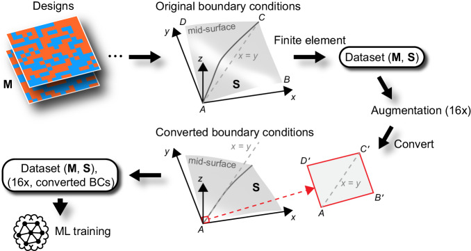
Fig. 2. Schematics of two boundary conditions (BCs): original BCs (Eq. (1)) and converted BCs (Eq. (2)).
M and S represent the random material distribution designs and corresponding actuated shapes, respectively. Using the original BCs, FE simulations are performed to generate the dataset, i.e., pairs of (M, S). The same BCs are then used to augment the dataset 16 times. Finally, the converted BCs are used to transform the generated dataset for the ML training. The quadrilateral AB’C’D’ (red) is taken to be the corner element face that lies on the mid-surface.

