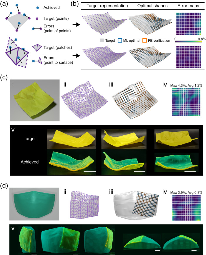
Fig. 7. Inverse design results for irregular target shapes or patches.
a Two representations of the target surface, the grid point representation (top) and patch representation (bottom), and corresponding approximation errors for the loss calculation, the point-pair distances (top) and the normal point-to-surface distances (bottom). b Comparison of design results obtained through the two strategies for an algorithmically generated irregular target shape. c Design result for the scanned target of a crumpled paper. A complete design-fabrication process is shown in Supplementary Movie 7. d Design result for the patch target of a surgical mask. Show in (c, d) include the raw target (i) and patch representation (ii), the optimized shape (iii) and error map (iv), and the 4D-printed, actuated shape (v). All scale bars: 10 mm. All the error maps are measured for the FE-evaluated actuated shapes versus the target, and the error values are relative to the edge length.

