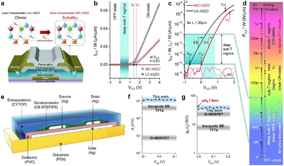
Figure 9.
Subthreshold Schottky-barrier thin-film transistors (SB-TFTs). (a) Schematic of a metal oxide-based inorganic SB-TFT. IGZO, indium-gallium-zinc-oxide; LC, less compensated; MC, more compensated. (b,c) Measured input characteristics in linear scale (b), indicating VT (the threshold voltage), and in logarithmic scale (c), indicating Vref (the reference voltage), respectively. IG, gate leakage current. (d) Conceptual color bar of output power consumption (Pout) for a 1 V supply, normalized with W (channel width), clearly indicating each operational regime. Frames a–d adapted with permission from ref 473. Copyright 2016 American Association for the Advancement of Science. (e) Schematic of an organic SB-TFT. CYTOP, a commercial fluoropolymer; C8-BTBT, 2,7-dioctyl[1] benzothieno[3,2-b][1]benzothiophene; PS, polystyrene; PVC, polyvinyl cinnamate; PEN, polyethylene naphthalate. (f,g) Comparison of intrinsic gain (f) and transconductance efficiency (g) of different transistors. Organic SB-TFTs have the best performance. MOSFET, metal-oxide-semiconductor field-effect transistor. Frames e–g adapted with permission from ref 198. Copyright 2019 American Association for the Advancement of Science.

