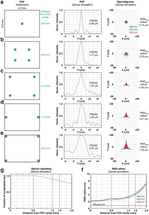
Extended Data Fig. 1 ∣. Wearable macroscopes with custom-compound microlenses have a predicted ~3–4 μm lateral resolution across a millimeter-scale FOV based on Zemax simulations.
a–e, Zemax simulations showing the optical system’s PSF (center) and spot diagrams (right) at different FOV positions (left), including 0 mm (a), 0.8 mm (b), 1.4 mm (c), 1.6 mm (d), and 2.0 mm (e) from the center. At a given FOV location, the RMS spot diagrams for 490 nm (blue), 525 nm (green), and 550 nm (red) are overlaid. RMSavg provides the average radius for these three wavelengths, falling within the wearable macroscope’s achromatic range (450–570 nm). f, RMS radius across the FOV for 490 nm (blue), 525 nm (green), and 550 nm (red). The dotted lines indicate the FOV positions shown in panels a–e. The small hump at field position 0.8 mm corresponds to the location of the field stop used to reduce aberrations in the outer portion of the FOV. g, Optical vignetting across the FOV. The dotted lines indicate the FOV positions shown in panels a–e. The decrease in light collection beyond field position 0.8 mm corresponds to the location of the field stop.

