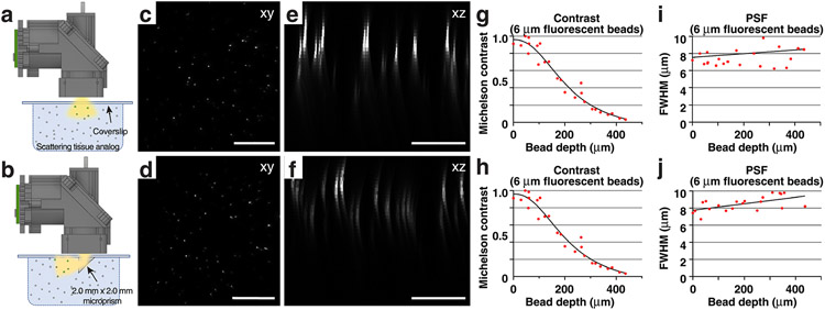
Extended Data Fig. 5 ∣. Wearable macroscopes with custom-compound microlenses offer a ~2.7 mm working distance permitting imaging through implanted microprisms.
a,b, Schematics showing the experimental approach for characterizing and comparing two imaging conditions in scattering tissue phantoms (Methods): Top, imaging through a coverslip; bottom, imaging through a coverslip with an attached 2.0 mm × 2.0 mm × 2.0 mm microprism (W × D × H) with a reflective, enhanced aluminum coating on the hypotenuse. c,d, Example images of tissue phantom embedded 6 μm-diameter fluorescent beads. Each image is a maximum intensity projection through a z stack acquired as shown in a–b by translating the wearable macroscope axially. Scale bar, 500 μm. e,f, Maximum intensity side projections of the acquired z stacks. Scale bar, 200 μm. g,h, Bead contrast as a function of imaging depth. Michelson contrast is defined as (peak − background)/(peak + background) and, therefore, unitless. i,j, Lateral FWHM of the 6 μm-diameter fluorescent beads as a function of imaging depth. All images are representatives from one sample. Images with similar properties were obtained across multiple independent samples.

