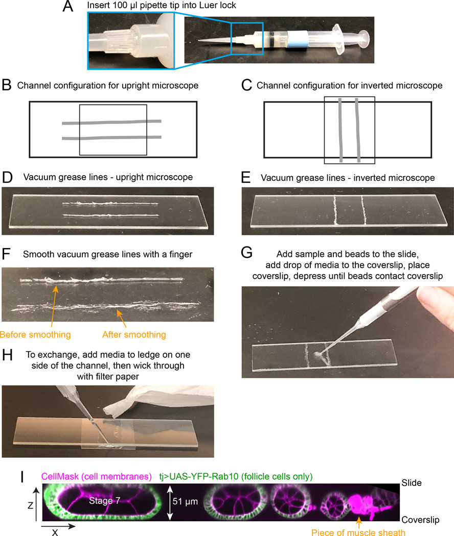
Fig. 2. How to construct flow chamber.
A. Vacuum grease-filled 10 ml syringe with a 100 μl pipette tip attached to the Luer lock in place of a needle. B and C. Diagram of flow chamber construction for an inverted or upright microscope. Light grey thick lines indicate where vacuum grease lines should be drawn on slide. Smaller rectangle indicates position of the 20 × 30 coverslip. D and E. Image of the desired spacing and thickness of vacuum grease lines. Note that these should be thin and you will likely have some gaps in the original lines. F. Image of the same vacuum grease line after smoothing it with finger (bottom). Now it is flatter and will require less manual compression when you add the coverslip. You should make sure there are no gaps that will allow leaks in the final line. G. Image showing where to initially add egg chambers and beads to slide. H. Image of the assembled and compressed flow chamber, showing where to add media to the coverslip ledge that extends past one edge of the channel, and image of torn filter paper being used to wick media through flow chamber. I. Zeiss Lattice Light Sheet volume of an ovariole compressed between slide and coverslip, supported by 51 μm diameter beads. A x-z projection is shown to highlight the compression of the stage 7 egg chamber that will hold it in place during medium exchanges.

