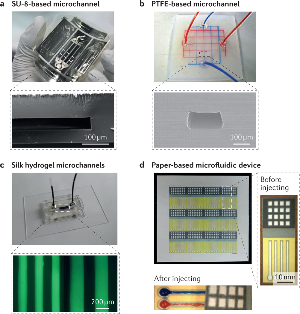
Figure 3 |. Representative materials for microfluidic devices.
a | A free-standing SU-8-based microfluidic sensor. The inset shows a cross-sectional scanning electron microscopy (SEM) image of a microchannel. b | A polytetrafluoroethylene (PTFE)-based microfluidic device with two-layer microchannels separated by a thin membrane. The inset shows a cross-sectional SEM image of the microchannel. c | Fabrication process of a two-layer silk hydrogel microfluidic device using gelatin moulding and layer-by-layer stacking methods. The inset shows optical micrographs of the minimal microchannel diameters achievable with the silk hydrogel microfluidic device. d | Paper-based 3D microfluidic device for multiple bioassays and sequential fluidic manipulation. The inset on the right shows a magnified view of the device before liquid injection, and that on the bottom shows the device after injection. Panel a is adapted with permission from REF. 42, Copernicus Publications. Panel b is adapted with permission from REF. 47, National Academy of Sciences. Panel c is adapted with permission from REF. 60, Elsevier. Panel d is adapted with permission from REF. 70, Elsevier.

