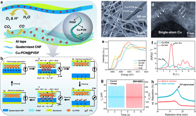
Fig. 1. Device design and characterizations of contact-electro-catalytic CO2RR.
a Schematic diagram showing the structure of TENG. b Schematic diagram of the TENG working cycle, highlighting the integrated TENG charge generation and catalytic charge consumption process during contact-electro-catalytic CO2RR. c SEM image of electrospun Cu-PCN@PVDF. d Spherical aberration-corrected STEM image of single-atom copper in Cu-PCN. e Cu K-edge X-ray absorption near edge structure (XANES) spectra of Cu-PCN and references. f Fourier-transformed k3-weighted Cu K-edge extended X-ray absorption fine structure (EXAFS) spectra of Cu-PCN and the reference. g Output current and voltage of the TENG at 99% RH. h Comparison of CO signal peaks before and after CO2RR tested by GC. Source data are provided as a Source Data file.

