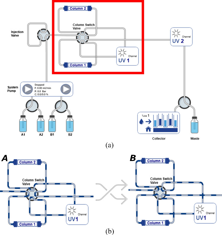
Fig. 1.
(a) Visualisation of alternative pumping recycling system by PurityChrom®6 software. In the red rectangle the recycling circuit is highlighted, which is made of two twin columns (column 1 and column 2) and a UV detector (UV1). (b) Representation of two flow paths generated by switching a 8-port-2-position valve. In configuration A the flow goes through column 1 to UV1 to column 2. In configuration B the flow goes through column 2 to UV1 to column 1

