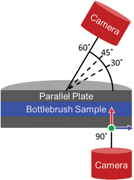
Fig. 2.
A schematic depicting the position of the microscope and camera setup relative to the sample during measurements. All images captured at 90° correspond to the 1–3 shear plane. The light source originates from the camera at each angle. The green, red, and blue arrows correspond to the flow, gradient, and vorticity directions, respectively.

