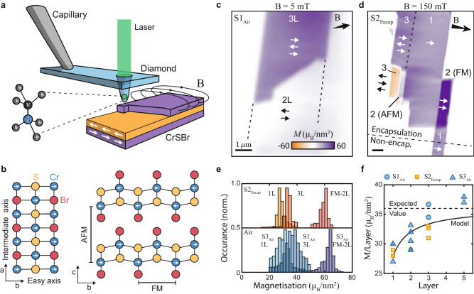
Fig. 1. Magnetic characterization of few-layer CrSBr.
a Illustration of the experiment involving an all-diamond tip containing a single-spin magnetometer that is scanned over the sample to spatially image magnetic stray fields. b Crystallographic structure of CrSBr, where the magnetic easy (intermediate) axis is aligned along the b(a)-axis of the crystal respectively. c Magnetization image of a non-encapsulated bilayer and trilayer flake (Sample 1, S1Air ), obtained in a low bias magnetic field ∣Bext∣ = 5mT. d Magnetization image of an encapsulated multi-layer flake (Sample 2, S2Encap ), obtained in a bias magnetic field ∣Bext∣ = 150mT strong enough to induce FM ordering in some bilayer sections. e Exemplary magnetization histograms of encapsulated (top panel) and non-encapsulated (bottom panel) flakes of different thicknesses taken from additional datasets. f Extracted magnetization per CrSBr layer for encapsulated (orange) and non-encapsulated (blue) flakes as a function of the number of layers. The dashed line is the expected value (36 μB/nm2) from bulk measurements and the solid black line is a simplified model fit (see text).

