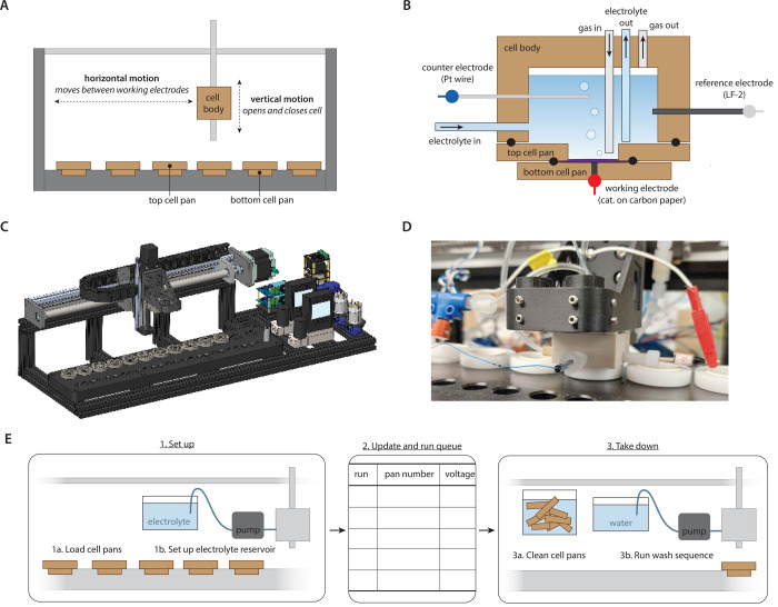
Figure 1.
Robot design for the automated experiments. (A) Schematic of operation, where vertical motion opens and closes a cell body on top of a pair of cell pans and horizontal motion moves the cell body to different cell pans. Together these motions allow automatic execution of a different experiment at each cell pan. (B) Schematic of cell geometry, where the cell body houses ports for working and counter electrodes as well as ports for electrolyte/gas flow in/out of the cell. The top and bottom cell pan sandwich a working electrode, which is pressed into a conducting pin. Blue, red, and gray dots indicate connections to the potentiostat. Seals between cell body and pans are made by o-rings, depicted as black circles. (C) CAD depiction of the overall robot design. (D) Photograph of the robot during operation, while an electrochemical experiment is being executed at one of the cell pans. (E) Schematic illustrating the operational workflow of the automated system.

