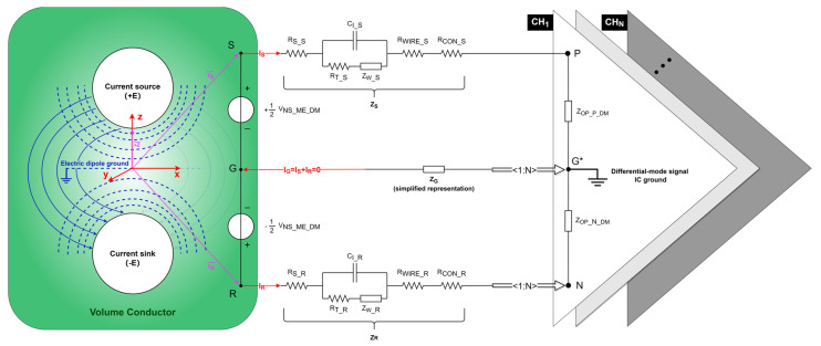
Figure 3.
Neural signal equivalent circuit in a differential recording setup. Equipotential surfaces (blue dashed curves) and streamlines of the current (blue solid curves) for an electric dipole (white circle) consisting of the current source (+E) and current sink (-E). Each vector (purple lines) references the coordinate system (red lines). represents the differential-mode neural signal captured from the electrolyte–electrode interface. Points , , and , respectively, represent the positions of the signal electrode, reference electrode, and ground electrode implanted in the cortex. , , and represent the path impedances of the signal, reference, and ground electrodes, respectively. Points , , and , respectively, represent the inputs of the positive, negative, and differential-mode signal IC ground of the OPA. , , and represent the path current through the signal, reference, and ground electrodes, respectively. and represent the equivalent input differential-mode impedance of the positive and negative input of the OPA, respectively. The amplifier shares one negative and one ground input for N recording channels.

