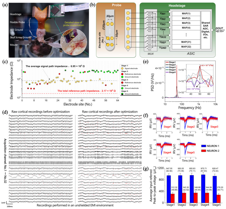
Figure 6.
(a) In vivo experiment recording setup and a detailed view of the flexible probe implantation. (b) System architecture of the configurable 32-channel neural recording system prototype. Left: schematic of electrode configuration in a single shank. Right: schematics of the circuit architecture for the headstage. MAPs, modular analog pixels. (c) Electrode impedance at 1 kHz. (d) Raw cortical recordings before and after optimization in an unshielded EMI environment. Red marks represent the time point of the neuron firing. Taking the acquisition results of No.7 as an example, (e) power spectral density (PSD) of raw cortical recordings, (f) input-referred voltage (IRV) of spike, and (g) input-referred peak-to-peak voltage of spike and standard deviation statistics are obtained in five stages.

