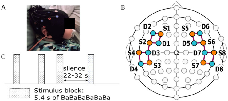
Figure 1.
fNIRS optode arrangement and stimulus presentation protocol. (A) A sleeping infant with a mounted fNIRS cap. (B) The arrangement of sources (orange circles) and detectors (teal circles) positioned over F3/4, F5/6, FC3/4, FC5/6, C5/6, T7/8, CP5/6, and TP7/8 according to the International 10–10 system. The purple lines represent channels formed by the source-detector pairs. (C) The stimulus presentation protocol used in this study.

