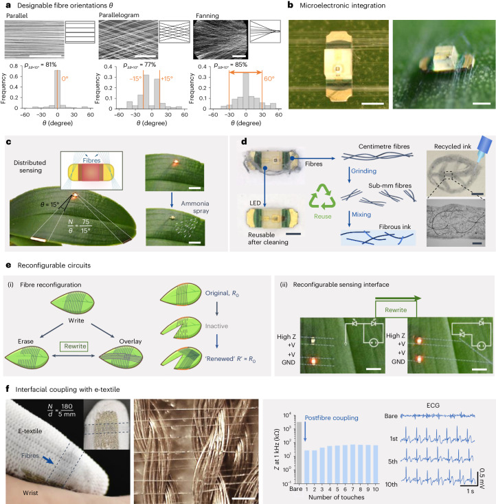
Fig. 5. Adaptable, versatile and reconfigurable fibre coupling.
a, Fibre tethering with designable fibre orientations (θ) is demonstrated by statistical analysis of fibre orientations θ with different fibre patterns, and the patterning accuracy (p∆θ=10°) is calculated by taking an 10°-offset (the width of the binning in the histogram) being an acceptable criterion for misalignment (a horizontal line is used as the 0° baseline for measuring all the fibre orientation angles). b, Photographs showing the top and profile views of fibre arrays connecting to the contacts of an LED (scale bars, 2 mm). c, Distributed bioelectronic fibres to connect with an LED on a plant leaf to warn environmental exposure of ammonia on the plant surfaces (where the dashed lines indicate the boundary of the fibre arrays, scale bars, 5 mm; typical results from independent experiments performed with n > 3 plants). d, Concepts for reusable and recyclable components, where the LED and bioelectronic fibres could be separated: the LED reused, and the fibres recycled into a feedstock to create conductive inks for 3D printing (line resistance at around 1 kΩ mm−1 dependent on filler concentration; scale bars from left to right, and top to bottom, 1 mm, 2 mm and 500 μm). e, Concepts for reconfigurable sensing interface. (ii) Schematics showing a fibre fabrication and reconfiguration process, where the ‘rewrite’ process could ‘renew’ the fibre sensing interface, while retaining similar levels of fibre array resistance between the original R0 and the ‘renewed’ R′ states and (ii) bioelectronic fibre arrays on the surface of a leaf that are written and rewritten to achieve a topological change in the sensing interface (for each fibre array ; scale bars, 5 mm; typical results from independent experiments performed n > 3 plants). f, An array of bioelectronic fibres deposited onto the finger region of an e-textile glove that reduce contact impedance by approximately two orders of magnitude, thus enabling biopotential monitoring (scale bar, 200 μm).

