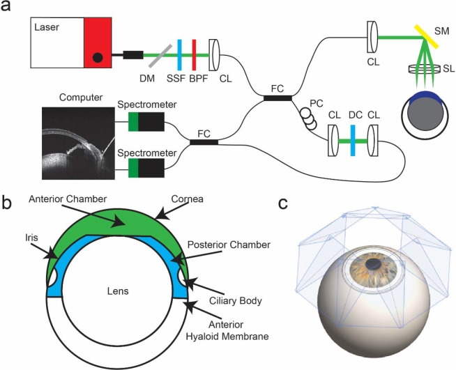
Fig. 1.
Experimental setup of vis-OCT imaging. a) Schematic of robotic vis-OCT. Light from an NKT laser is filtered by a dichroic mirror (DM), spectral shaping filter (SSF), and bandpass filter (BPF). The output light is coupled into a collimator (CL) and split by a 90:10 fiber coupler (FC). The reference arm includes a polarization controller (PC) and dispersion compensation (DC). Light in the sample arm is scanned by a galvanometer scanning mirror (SM) before being focused by a 25-mm scan lens (SL). The interference signal is split by a 50:50 fiber coupler (FC) into two spectrometers. b) Schematic cross-section of the mouse eye with the anterior chamber shaded in green and the posterior chamber in blue. c) Eight vis-OCT volumes, with scan planes perpendicular to the incident vis-OCT beam shaded in blue, are acquired around the eye.

