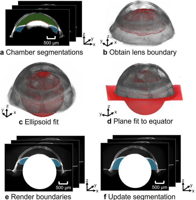
Fig. 4.
Workflow for identifying the posterior boundary of posterior chamber. a) Chamber segmentations were used to obtain the posterior boundary of the anterior chamber (green) and the interior boundary of the posterior chamber (blue). b) These boundaries were taken to coincide with the anterior surface of the lens. c) An ellipsoid (red) was fit to the lens’s upper boundaries. The center of the ellipsoid and the optical axis of the eye were used to d) generate a plane at the equator of the eye, approximating the location of the anterior hyaloid membrane. e) The posterior border of the reconstructed posterior chamber in the montaged B-scans is f) updated with the estimated position of the anterior hyaloid membrane.

