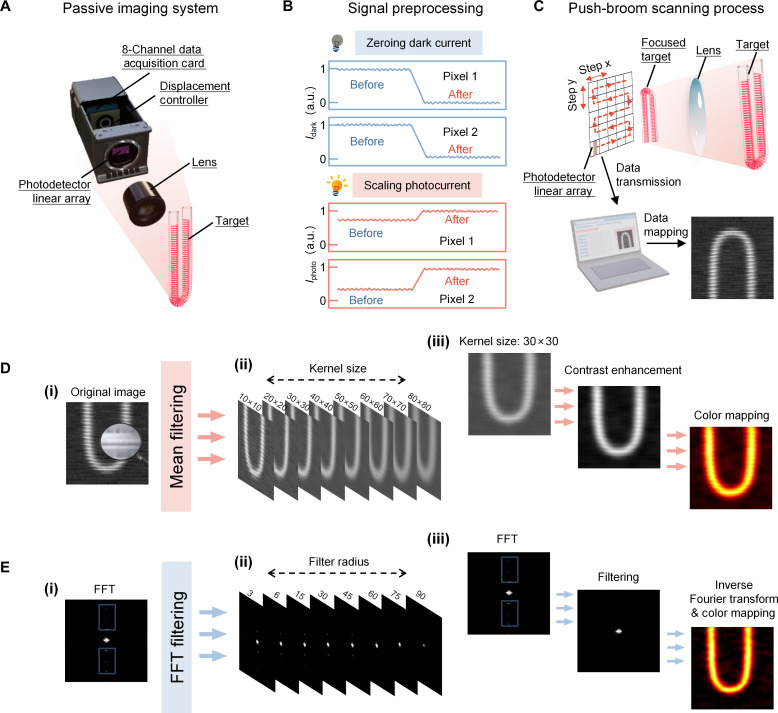
Fig. 4. Room temperature push-broom scanning passive of vdWs photodetector linear array and nonuniformity correction of the image.
(A) Schematic diagram of the eight-channel passive imaging system, where the stepper motor drives the detector to the set XY position, and the photoresponse signal is collected by an eight-channel data acquisition card. (B) Schematic diagram of the signal preprocessing includes zeroing dark current and scaling photocurrent. (C) Schematic diagram of push-broom scanning process, results were mapped in real-time on a computer. (D) Process of nonuniformity correction of the image using mean filtering. Original image (i); filtered image with different kernel sizes (ii); contrast enhancement and color mapping after filtering (iii). (E) Process of nonuniformity correction of the image using FFT filtering. Frequency spectrum of the original image after FFT (i); filtered image with different filter radii (ii); inverse Fourier transform and color mapping after filtering (iii).

