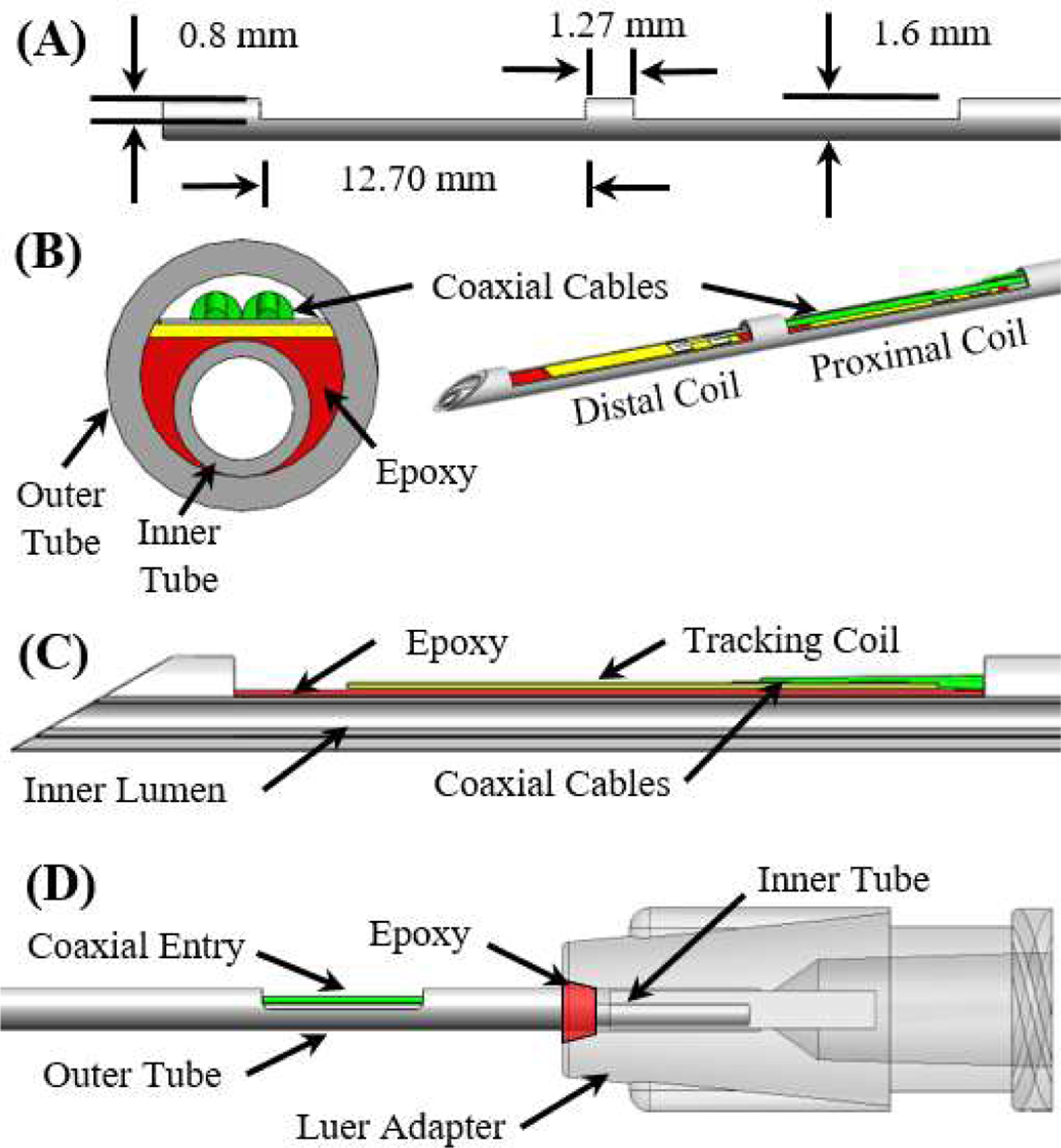
Fig. 1.

(A) A side view of the outer tube after the machining operations. (B) Front cross-section and isometric view of the MR-tracked needle assembly at the distal end. (C) Side cross-section view of the distal end of the injection needle assembly (proximal coil not visualized). (D) Side view of the proximal end of the needle assembly.
