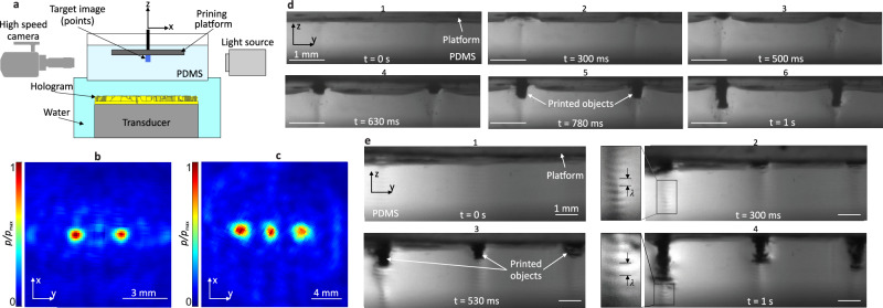
Fig. 3. Close observation of the HDSP printing process employing high-speed imaging.
a Side view of the observation setup including a high-speed camera to capture the HDSP printing process. b, c Normalized measured pressure maps of designed two- and three-spot pressure images, respectively. The gap between each two spots is 3 mm in (b) and 4 mm in (c). d Footage of high-speed imaging for two spots being printed with HDSP process during 1 s insonication. e Footage of high-speed imaging for three-spot printing during 1 s insonication. In all cases the platform (image plane) is designed to be 20 mm away from the transducer, printing parameters: OD = 25 mm, P = 5 W, f0 = 2.24 MHz, DC = 50%.

