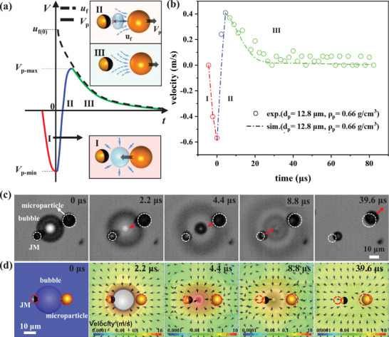
Figure 2.

Illustration of the BMT principle. The principle relies on the transient velocity variation of the target microparticle in response to the inertial impact from the bubble collapse when a JM–bubble–particle configuration is established. a) Schematic diagram illustrating the three‐stage velocity variation Vp of the target microparticle. In stage I (red), the microparticle retracts into the bubble cavity following the collapse. In stage II (blue), the transient hydrodynamic flow propels the microparticle strongly, resulting in a positive change in velocity. In stage III (green), the microparticle gradually decelerates as it interacts with the surrounding fluid flow. The dashed curve depicts the decay of the ambient fluid velocity uf . b) Measured velocity variation during stages II and III of a microparticle (with radius Rp = 6.4 µm, density ρp = 0.66 g cm−3) impacted by the BMT, compared with the dashed curve obtained from numerical simulation, indicating good agreement. c) Experimental snapshots (bottom view from the inverted microscope, see SM Video S1 (Supporting Information), recorded by an ultra‐high‐speed camera at 450 000 fps) capturing a BMT during bubble collapse, with white circles denoting the initial position of the target microparticle. d) Snapshots from numerical simulation showing the flow field and the motion of the microparticle at the same times as in (c). The red dashed circles display the original positions of the JM and the microparticle. The simulation perfectly reproduces the motions of both JM and the microparticle in experiment shown in (c).
