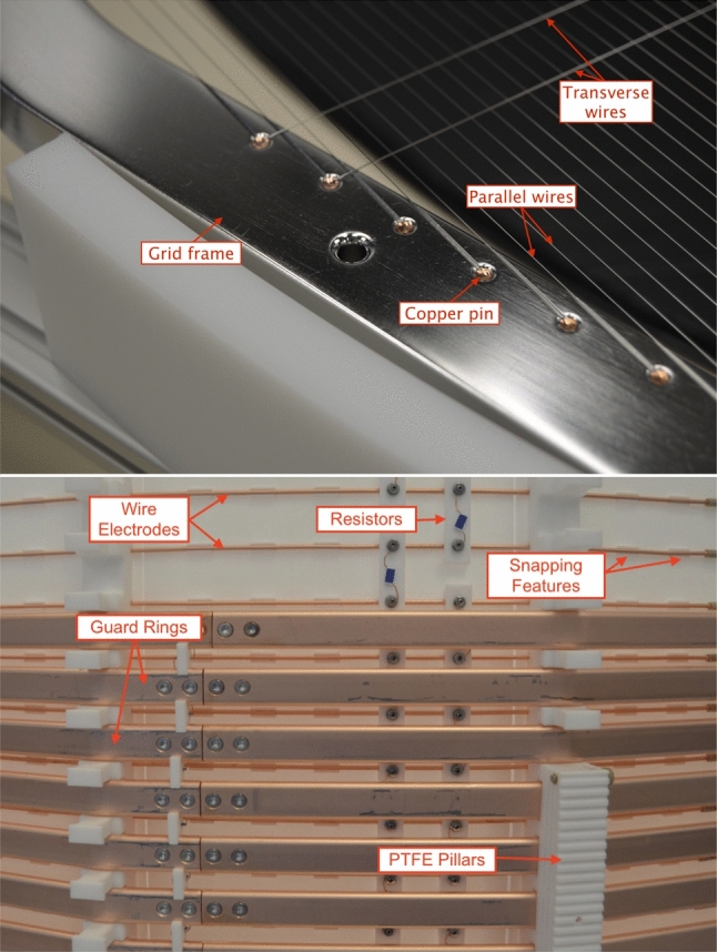
Fig. 7.

(top) The electrode wires are individually fixed by copper pins to the electrode frames (here: anode). Two transverse wires, installed to reduce sagging, are shown as well. (bottom) Detailed outside view of the TPC field-shaping elements during installation: the massive guard rings (15 mm height) and the thinner wire field electrodes (2 mm diameter) are installed at half pitch at different distances from the 3 mm thick PTFE reflectors. The guard electrodes consist of two pieces fixed together by two M3 SS bolts at each junction. The other two bolts are used to fix the guard-ring resistor chain (installed within the guard rings). Also visible are the 5 G resistors on PTFE supports connecting the wire field electrodes
