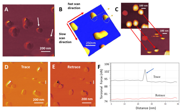
Figure 9.
AuNP movement is displayed by ‘cut’ particle appearance, Set Point 40nN. (A) Lateral deflection trace scan of AuNPs on MePPOx, and the two white arrows show the cut-off particles. The white arrows highlight the two AuNPs that exhibit the cut-off effect. (B) Sb particles on HOPG [69]. (C) AuNPs in contact mode before and during their interaction with the cantilever tip. The red arrows follow before and during the cut-off of three of the individual AuNPs, comparing the AM mode scan of the AuNP surface to the subsequent contact mode scan confirming the ‘cut’ appearance and AuNP movement. The yellow dotted lines around the two cut-off AuNPs, show the actual size of the NPs if they had not moved. In lateral deflection (D) trace and (E) retrace scans, the white vertical lines highlight where the 2D plot was conducted. (F) A 2D plot over the region of AuNP movement. The blue arrow signifies the increase in force experienced by the cantilever tip at the point of AuNP movement.

