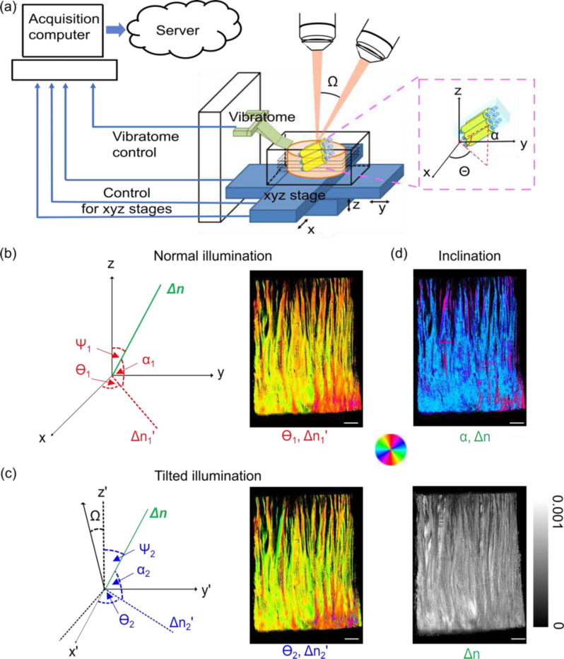
Fig. 1.
Computational optimization of true birefringence vector by normal and one tilted illumination. (a) System schematic. The insert shows the in-plane and through-plane () orientations of fiber tracts. (b) The angle definitions in the normal illumination incidences (left) and the orientation images obtained from this incidence (, right). (c) The angle definitions in the tilted illumination incidences (left) and the corresponding orientation images (, right). (d) The computational retrieved inclination angle image (, right). The angles of orientation in (b)-(d) are indicated by the color wheel. The brightness of the images is modulated by corresponding apparent birefringence , and the true birefringence, . The intensity of the true birefringence image is indicated by the scale bar in (d). Sclar bars: 1 mm.

